Bell & Gossett S14334B Technologic 5500 Series Variable Primary Pump and Valve Controller User Manual
Page 26
26
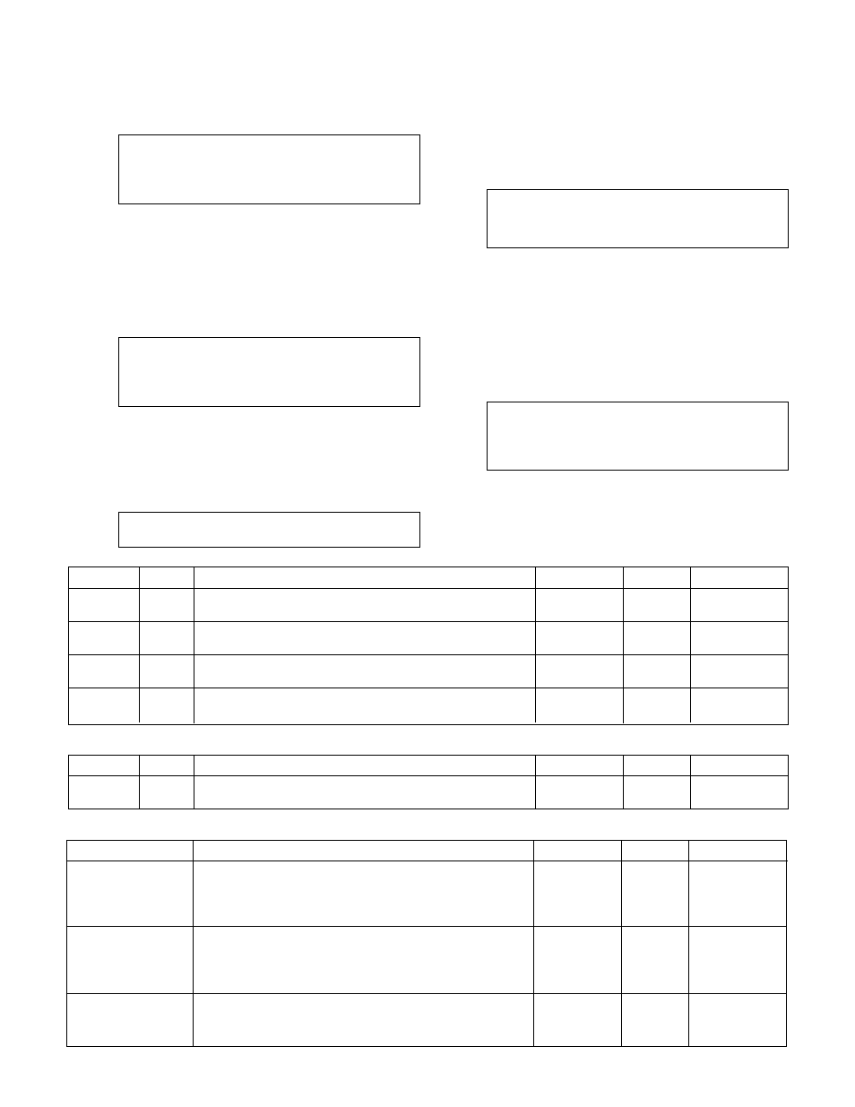
Press the numeric key for the chiller you wish to
setup. The chiller number is limited to the maximum
number of chillers. Press ENTER to proceed with the
setup. The display will show:
Chiller # #
Enable/Disable: #
1 = Enable 0 = Disable
Press PROCESS VARIABLE/1 and ENTER if the chiller
will be enabled. If the Chiller is enabled, then the
controller will go to the Chiller Setup screen shown
immediately below.
Press NO/0 and ENTER if the chiller will be disabled.
If the chiller is disabled, then the controller will skip
the following Chiller Setup screen.
Chiller # #
DP Max ## Min # Or
Flow Max # Min #
Ok ? (Y/N)
To accept the values shown and proceed, press
YES/7 and ENTER. To edit the fields, press NO/0
and ENTER. Table 29 gives a description of the Chiller
Setup variables.
Now the display will show:
Do Another ? (Y/N)
Press YES/7 and ENTER to set up another chiller.
Press NO/0 and ENTER to return to the Enbl/Disbl
Chiller screen shown at the beginning of this section.
4.6.2
Chiller's Run Tmr
From the Chiller Setup Menu, shown in section 4.6,
press SET POINT/2 and ENTER to get to the Chiller
Run Timer screen shown below.
Chiller Minimum
Run Timer ### min
Ok ? (Y/N)
To return to the Chiller Setup Menu, shown in section
4.6, press YES/7 and ENTER. To edit the chiller mini-
mum run timer, press NO/7 and ENTER. See Table
30 for a description of the Run Timer.
4.6.3
Isolation Valve
From the Chiller Setup Menu, shown in section 4.6,
press SETUP/3 and ENTER to get to the Chiller
Isolation Valve screen shown below.
Monitor Valve ? (Y/N)
Control Valve ? (Y/N)
Vlv Close Delay ? (Y/N) s
OK ? (Y/N)
To return to the Chiller Setup Menu, shown in section
4.6, press YES/7 and ENTER. To edit the chiller iso-
lation valve, press NO/7 and ENTER. See Table 31
on next page for a description of the Isolation Valve
variables.
Variable
Unit
Description
Default Value
Range
Field Value
DP Max
PSID
Maximum Differential Pressure prior to requesting to
18
0-999
stage another chiller.
DP Min
PSID
Minimum Differential Pressure to be maintained for the
5
0-999
selected chiller.
Flow Max
GPM
Maximum Flow prior to requesting to stage another
0
0-9999
chiller
Flow Min
GPM
Minimum Flow to be maintained for the selected
0
0-9999
enable chiller
Table 29: Chiller Setup Variables
Variable
Unit
Description
Default Value
Range
Field Value
Run
min
Request to destage chiller will not occur until chiller's
10
0-999
Timer
minimum run timer has expired
Table 30: Chiller Run TMr Variable
Variable
Description
Default Value
Range
Field Value
Monitor Valve
A DI signal is supplied from the limit switch on the valve.
N
Y or N
When the switch is closed, the valve is open. If Y is
selected, the pumps will not be allowed to start if all of
the isolation valves are closed.
Control Valve
A DO signal is supplied to control the actuator on the
N
Y or N
isolation valve. When the output is closed, the valve is
to open. Note: the isolation valve must be monitored
if it is controlled.
Vlv Close Delay
Timer to delay closing the isolation valve after stopping
5
0-999
the chiller. This variable is only used for dedicated pump
to chiller systems.
Table 31: Isolation Valve Variables