Bell & Gossett S14334B Technologic 5500 Series Variable Primary Pump and Valve Controller User Manual
Page 19
19
4.3.5
Bypass Setup
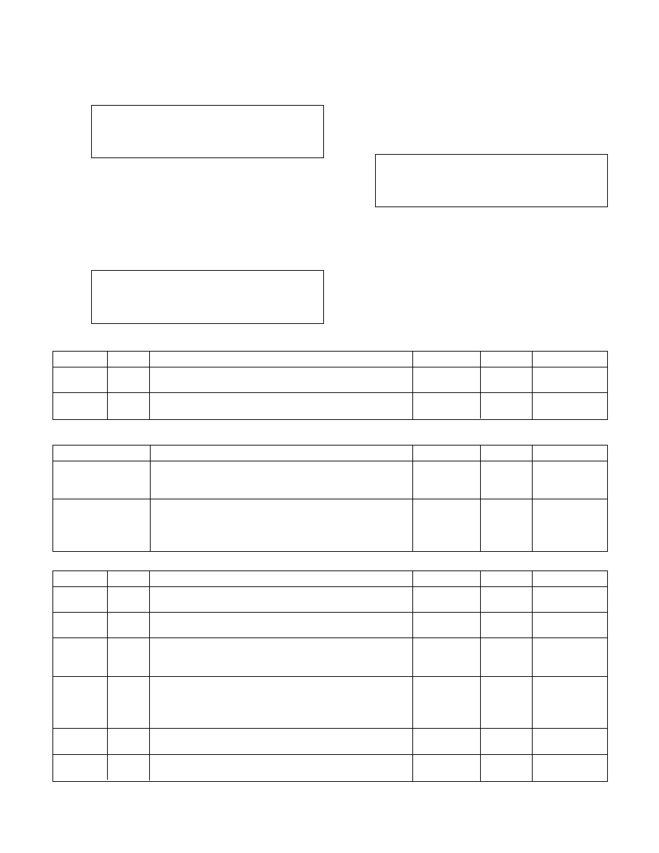
From the System Setup Menu, shown in section 4.3,
press F1/LOG/5 and ENTER to get to the Bypass
Setup screen shown below.
No of AFDs Fail to
go to bypass: #
No of Pumps go to
bypass: # Ok ? (Y/N)
To return to the System Setup Menu, shown in sec
-
tion 4.3, press YES/7 and ENTER. To edit the fields,
press NO/0 and ENTER. See Table 15 for a descrip-
tion of the Bypass Setup variables.
4.3.6
AFD Setup
From the System Setup Menu, shown in section 4.3,
press F2/6 and ENTER to get to the AFD Setup
screen shown below.
AFD Min/Max = ## / ###
Reset Tm/No = ### / ##
All PV Fail Spd = ###
# of Pumps = # Ok ? (Y/N)
To return to the System Setup Menu, shown in sec
-
tion 4.3, press YES/7 and ENTER. To edit the fields,
press NO/0 and ENTER. See Table 16 for a descrip-
tion of the AFD Setup variables.
4.3.7
Date/Time Setup
From the System Setup Menu, shown in section 4.3,
press YES/7 and ENTER to get to the Date/Time
Setup screen shown below.
MM/DD/YYYY HH:MM
Display 24 Hr Fmt: ? (Y/N)
Daylite Saving Tm: ? (Y/N)
Ok ? (Y/N)
To return to the System Setup Menu, shown in sec
-
tion 4.3, press YES/7 and ENTER. To edit the fields,
press NO/0 and ENTER. See Table 17 on next page
for a description of the Date/Time Setup variables.
Variable
Description
Default Value
Range
Field Value
No of AFDs Fail to
Number of AFDs that are required to fail prior to running
0
0-6
go to bypass
the pump(s) across the line. Generally the number of
drives controlled by the system.
No of Pumps go to
After the number of AFDs fail as per above, this item
0
0-6
bypass
determines the maximum number of pumps allowed to
start in bypass. Before setting for all available pumps
confirm that the system can handle the flow.
Table 15: Bypass Variables
Variable
Unit
Description
Default Value
Range
Field Value
AFD Min
%
Percent speed at which the AFD will operate with the
30
0-99
speed follower signal minimized (0V)
AFD Max
%
Percent speed at which the AFD will operate with the
100
0-999
speed follower signal maximized (10V)
Reset Tm
s
Time it takes the AFD to reset after detecting a self
0
0-999
protecting fault. Refer to the AFD manufacturer's setup
manual for proper setup.
Reset No
Number of resets the AFD will attempt after detecting a
0
0-10
self protecting fault prior to determining that the AFD is in
the fault condition. Refer to the AFD manufacturer's setup
manual for proper setup
All PV
%
Percent speed for the drive(s) to operate at in the event
100
0-100
Fail Spd
that all zones fail
# of
Number of pumps that should operate at the above
1
0-6
Pumps
speed in the event that all zones fail
Table 16: AFD Variables
Variable
Unit
Description
Default Value
Range
Field Value
Time
hr
Enter the time between automatic alternation cycles.
0
0-999
Between
s disables automatic alternation.
Duration
s
The amount of time allowed to decelerate the running
20
0-999
pump(s) and start the new lead pumps
Table 14: Alternation Variables