Bell & Gossett S14334B Technologic 5500 Series Variable Primary Pump and Valve Controller User Manual
Page 15
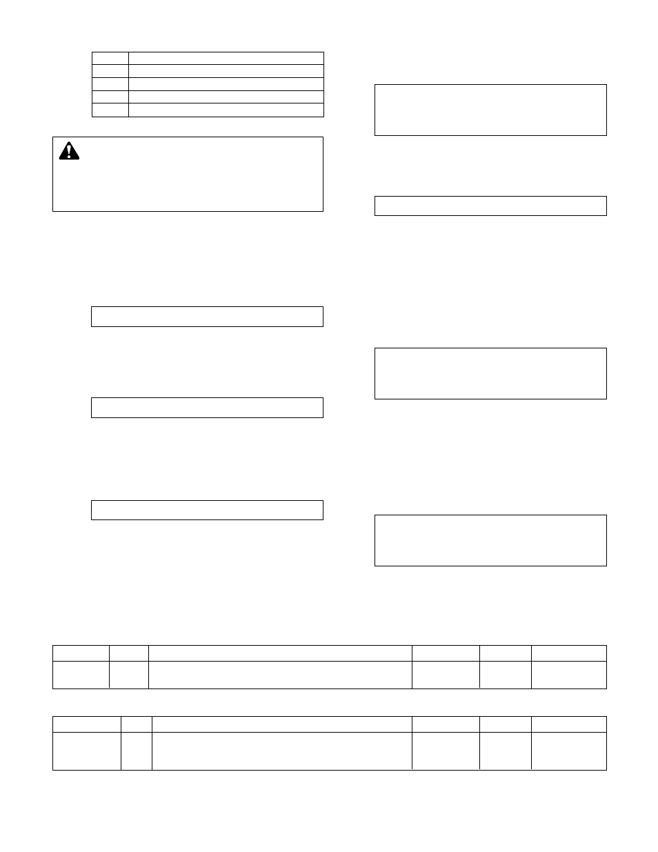
Table 4: Pump Off Delay Variables
15
State
Description
N/A
pump not available as defined by setup
Rdy
pump available, not running
On
pump is running
Off
pump disabled, will not be allowed to start
Table 3: Pump States
Press YES/7 and ENTER to accept pump configura
-
tion and return to setup selection screen.
Press NO/0 and ENTER to setup any pumps.
4.2.2
Number of Pumps
If NO was selected in section 4.2.1, the following
displayed:
Total # Pumps = #
Press the numeric key for the total number of pump
(1 to 6 pumps). Press ENTER to continue.
4.2.3
Edit Pump
The display will now show the following:
Edit Pump ? (Y/N)
Press YES/7 and ENTER to set up any pumps. Press
the NO/0 and ENTER keys to return to the Pump
Setup Menu shown in section 4.2.
4.2.4
Edit Pump Number
The display will now show the following:
Edit Pump # #
Press the numeric key(s) for the pump you wish to
setup. The pump number is limited to the maximum
numbers of pumps. Press the ENTER key to proceed
with the setup.
4.2.5
Enable/Disable Pump
The display will now show the following:
Pump # #
Enable/Disable: #
1 = Enable 0 = Disable
Press PROCESS VARIABLE/1 and ENTER to enable
the pump. Press NO/0 to disable a pump.
4.2.6
Do Another
The screen will now display:
Do Another ? (Y/N)
Press YES/7 and ENTER to setup another pump.
Return to section 4.2.4 and repeat for all remaining
pumps.
Press NO/0 and ENTER to return to the Pump Setup
Menu, shown in section 4.2.
4.2.7
Pump Off Delay
From the Pump Setup Menu, shown in section 4.2,
press SET POINT/2 and ENTER to edit the pump off
time delay. The display will show:
Pump Off Time Delay
# Min.
Exit ? (Y/N)
Press NO/0 and ENTER to edit the value. Press
YES/7 and ENTER to return to the Pump Setup Menu
shown in section 4.2. See Table 4 for a description of
the Pump Off Time Delay. Note: This time delay only
applies to dedicated pump to chiller systems.
4.2.8
Lag Pump Run Timer
From section 4.2, press SETUP/3 and ENTER to edit
the lag pump run timer. The display will show:
Lag Pump Full Speed
Minimum run time
# Sec.
Exit ? (Y/N)
Press NO/0 and ENTER to edit the value.
Press YES/7
and ENTER to return to section 4.2. See Table 5 for a
description of the variable. Note: This variable only
applies to dedicated pump to chiller systems.
Variable
Unit
Description
Default Value
Range
Field Value
Pump off
min
The delay prior to turning a pump off after losing the
1
0-99
time delay
chiller start signal.
Table 5: Lag Pump Run Timer Variable
Variable
Unit
Description
Default Value
Range
Field Value
Lag pump
s
The amount of time a pump will run at full speed when
0
0-999
full speed
an additional chiller is turned on. 0 disables this function.
min run time
DANGER: High voltage 3 phase power can kill.
Pumps can start automatically. Disconnect and lock-
out power prior to servicing pumps.
FAILURE TO FOL
-
LOW THESE INSTRUCTIONS WILL RESULT IN SERIOUS
PERSONAL INJURY, DEATH, AND/OR PROPERTY
DAMAGE.