Bell & Gossett S14334B Technologic 5500 Series Variable Primary Pump and Valve Controller User Manual
Page 18
18
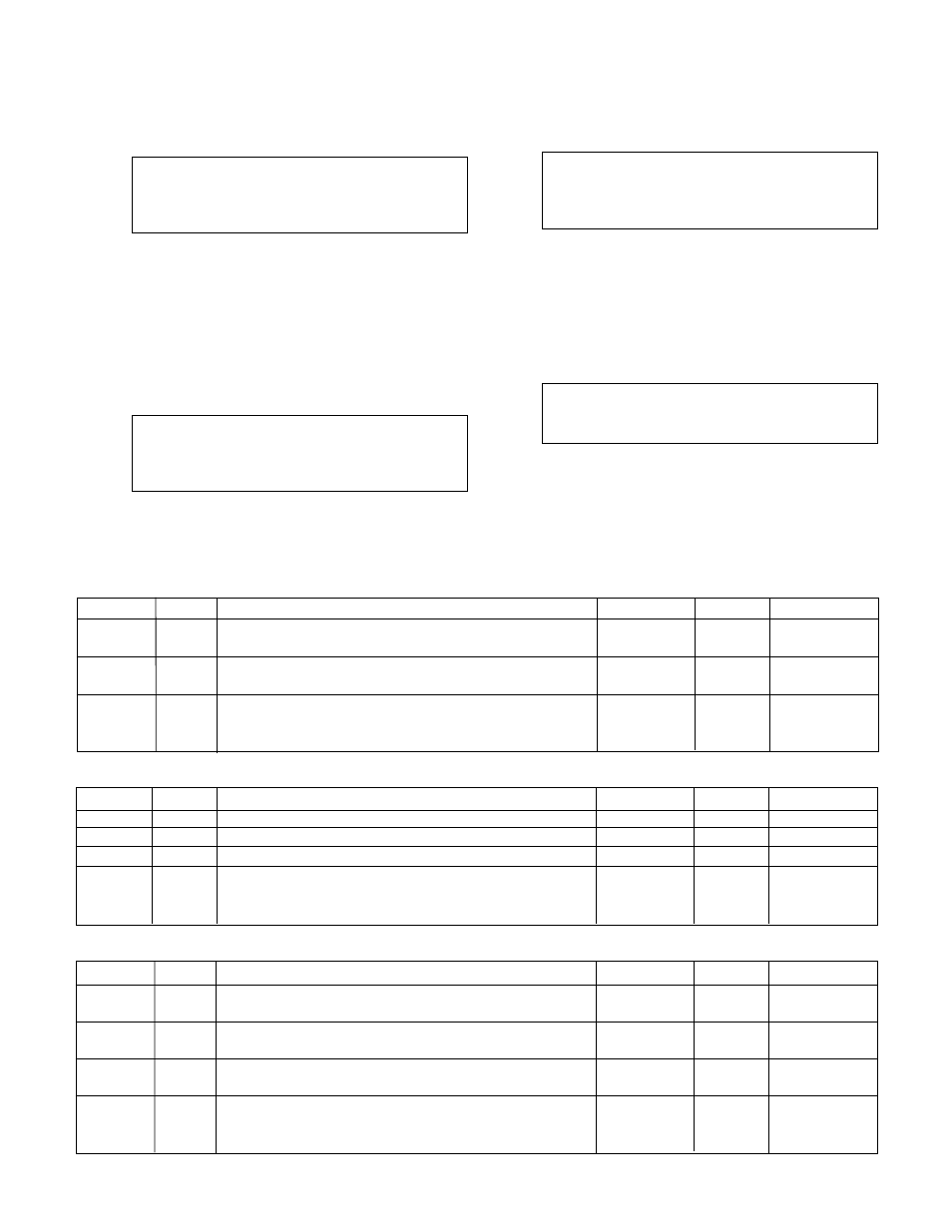
Variable
Unit
Description
Default Value
Range
Field Value
AFD Fail
s
Proof timer prior to setting the AFD fail alarm
20
0-999
Pr Tm
Pump Fail
s
Proof timer prior to setting the pump fail alarm
30
0-999
Pr Tm
O.L. Fail
s
Proof timer prior to setting the O.L. fail alarm
3
0-999
Pr Tm
Reset Tm
s
Time delay between pressing the RESET key and
10
0-999
restarting the pumps in variable speed mode, allows
for pump deceleration
Table 13: Alarm Variables
4.3.1.4 EOC Destage
From the Stage/Destage Menu, shown in section
4.3.1, press ALTERNATION/4 and ENTER to get to
the EOC Destage screen shown below.
Destage Flow: ##%
Destage Pr Tm: ##s
Tm Forced Destg: #m
Ok ? (Y/N)
To edit the fields, press NO/0 and ENTER. To return
to the Stage/Destage Menu, shown in section 4.3.1,
press YES/7 and ENTER. See Table 11 below for a
description of the EOC Destage variables.
4.3.2
PID
From the System Setup Menu, shown in section 4.3,
press SETPOINT/2 and ENTER to get to the PID
screen shown below.
PID-P ### PID-I #
PID-D #
Ramp Timer ###s
Ok ? (Y/N)
To edit the fields, press NO/0 and ENTER. To return
to the System Setup Menu, shown in section 4.3,
press YES/7 and ENTER. See Table 12 below for a
description of the PID variables.
4.3.3
Alarms Setup
From the System Setup Menu, shown in section 4.3,
press SETUP/3 and ENTER to get to the Alarms
Setup screen shown below.
AFD Fail Pr Tm: ##s
Pump Fail Pr Tm: ##s
O.L. Fail Pr Tm: ##s
Reset Tm: 10s Ok ? YN
To return to the System Setup Menu, shown in sec
-
tion 4.3, press YES/7 and ENTER. To edit the fields,
press NO/0 and ENTER. See Table 13 for a descrip-
tion of the Alarms Setup variables.
4.3.4
Alternation Setup
From the System Setup Menu, shown in section 4.3,
press ALTERNATION/4 and ENTER to get to the
Alternation Setup screen shown below.
Time Between: # Hr.
Duration: ##s
Ok ? YN
To return to the System Setup Menu, shown in sec
-
tion 4.3, press YES/7 and ENTER. To edit the fields,
press NO/0 and ENTER. See Table 14 on next page
for a description of the Alternation Setup variables.
Note: Alternation can also be accomplished manually.
See section 5.10.
Variable
Unit
Description
Default Value
Range
Field Value
PID-P
N/A
Proportional value
200
0-999
PID-I
N/A
Integral value
5
0-999
PID-D
N/A
Derivative value
2
0-999
Ramp
s
The amount of time it takes to get a pump up to full speed
100
25-100
Timer
immediately after starting a chiller. This variable only
applies to dedicated pump to chiller systems.
Table 12: PID Variables
Variable
Unit
Description
Default Value
Range
Field Value
Destage
%
Percentage of max flow at which the lag pump is
45
0-100
Flow
destaged
Destage
s
Proof timer prior to destaging lag pump
30
0-999
Pr Tm
Tm
m
Time elapsed before a forced destage
0
0-100
Forced
Destg
Table 11: EOC
Destage Variables