Bell & Gossett S14334B Technologic 5500 Series Variable Primary Pump and Valve Controller User Manual
Page 27
27
4.7
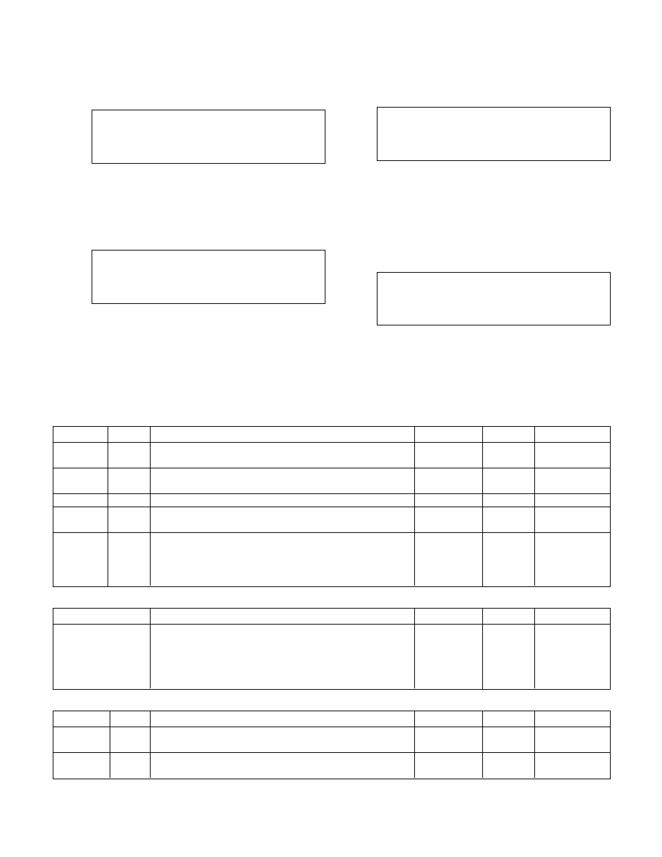
Bypass Valve Setup
From the Setup Selection Menu, shown in section 4,
press YES/7 and ENTER to get to the Bypass Valve
Setup Menu shown below.
Selection: # Exit =0
1 = Byps Valve Setting
2 = Byps Operat. Mode
3 = Timers
Press the appropriate numeric key and ENTER.
4.7.1
Bypass Valve Setting
From the Bypass Valve Setup Menu, shown in sec
-
tion 4.7, press PROCESS VARIABLE/1 to get to the
Bypass Valve Setting screen shown below.
Min Opening = ##%
Max Opening = ##%
Step = ##% Volts: ?
Rev ?(Y/N) Ok ? (Y/N)
To return to the Bypass Valve Setup Menu, shown in
section 4.7, press YES/7 and ENTER. To edit the
values shown, press NO/7 and ENTER. See Table 32
for a description of the Bypass Valve Opening variables.
4.7.2
Bypass Valve Operation Mode
From the Bypass Valve Setup Menu, shown in sec
-
tion 4.7, press SET POINT/2 to get to the Bypass
Valve Operation Mode screen shown below.
Bypass Valve
Operation Mode #
1 = Auto
2 = Manual
Ok ? (Y/N)
To return to the Bypass Valve Setup Menu, shown in
section 4.7, press YES/7 and ENTER. To edit the
value shown, press NO/7 and ENTER. See Table 33
for a description of the Operation Modes.
4.7.3
Timers
From the Bypass Valve Setup Menu, shown in sec
-
tion 4.7, press SETUP/3 to get to the Timers screen
shown below.
Bypass Valve Timers
Opening Timer ##s
Closing Timer ## s
Ok ?
To return to the Bypass Valve Setup Menu, shown in
section 4.7, press YES/7 and ENTER. To edit the
values shown, press NO/7 and ENTER. See Table 34
for a description of the Timer variables.
Variable
Unit
Description
Default Value
Range
Field Value
Min
%
Minimum Valve Position
0
0-100
Opening
Max
%
Maximum Valve Position
100
0-100
Opening
Step
%
The increment by which the valve will modulate
3
0-100
Volts
N/A
Select "Y" if the signal to the bypass valve is 0-10V.
N
Y/N
Select "N" if the signal is 4-20mA.
Rev
N/A
Select "N" if the signal to the bypass valve is not
N
Y/N
reversed (4mA or 0V = closed, 20mA or 10V = open),
Select "Y" if the signal to the bypass valve is reversed
(20mA or 10V = closed, 4mA or 0V = open).
Table 32: Bypass Valve Opening Variables
Table 33: Bypass Valve Operation Modes
Variable
Unit
Description
Default Value
Range
Field Value
Opening
s
Time delay between opening the bypass valve by
3
0-30
Timer
the Step.
Closing
s
Time delay between closing the bypass valve by
5
0-30
Timer
the Step.
Variable
Description
Default Value
Range
Field Value
Bypass Valve
Select "1" for automatic operation. In automatic operation
1
1,2
Operation Mode
the Logic controls the valve opening to protect the chiller
minimum flow. Select "2" for manual operation. In manual
operation use the Bypass Valve Position screen, shown in
section 5.1.10, to control valve position.
Table 34: Timers Variables