Bell & Gossett S14334B Technologic 5500 Series Variable Primary Pump and Valve Controller User Manual
Page 16
16
4.2.9
Low Load Transfer
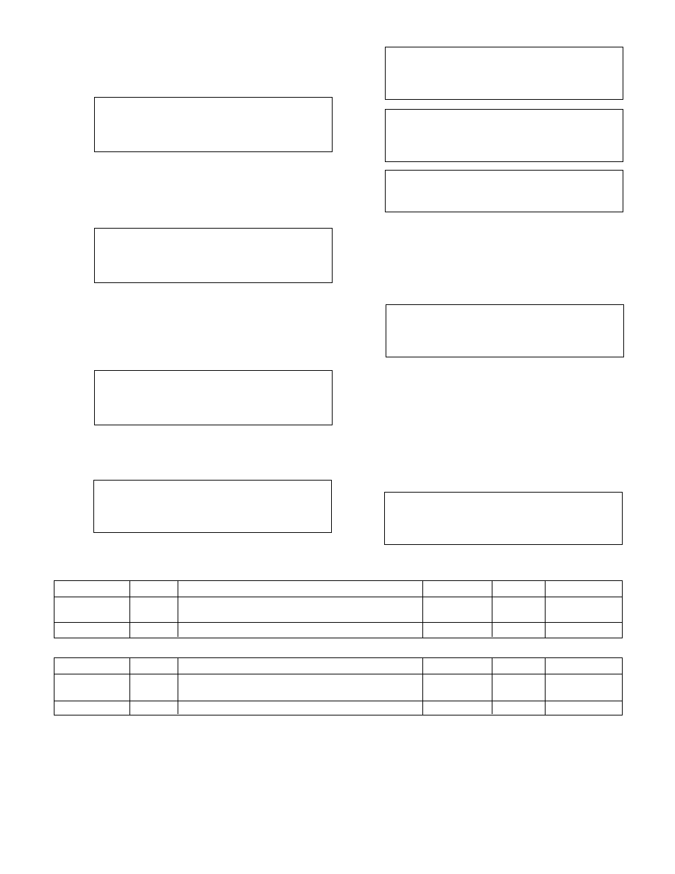
From section 4.2, press 4 and ENTER to get to the
Low Load Transfer screen shown below.
Low Load Transfer
Point ### % Speed
Enable?
Exit (Y/N)
See Table 6 for a description of the Low Load Trans-
fer variables.
4.2.10
High Load Transfer
From section 4.2, press 5 and ENTER to get to the
High Load Transfer screen shown below.
High Load Transfer
Point ### % Speed
Enable?
Exit (Y/N)
See Table 7 for a description of the HIgh Load Trans-
fer variables.
4.3
System Setup Menu
From the Setup Selection Menu, shown in section 4,
press the SETUP/3 key and ENTER to get to the
System Setup Menu shown below.
Selection: #
0 = Exit
1 = Stage/De-stage
2 = PID
3 - Alarms
Press NEXT SCREEN key or PREV. SCREEN to view
the neighboring pages in the System Setup Menu.
There are five screens in this menu. The remaining
screens are shown below.
Selection: #
0 = Exit
4 = Alternation
5 = Bypass
6 = AFD
Selection: #
0 = Exit
7 = Date/Time
8 = Password
9 = I/O Setup
Selection: #
0 = Exit
10 = Communication
11 = Special Functions
12 = Set Bright/Constr
Selection: #
0 = Exit
13 = Save to Flash
14 = Load from Flash
Use the appropriate numeric key to select the setup
menu desired, and press the ENTER key.
4.3.1
Stage/Destage Menu
From the System Setup Menu, shown in section 4.3,
press PROCESS VARIABLE/1 and ENTER to get to
the Stage/Destage Menu shown below.
Selection: #
1 = PV Stg
2 = PV Destg
3 = EOC Stg
4 = EOC Dest
0 = Exit
Press the appropriate numeric key and ENTER to
complete the setup, or press NO/0 to exit back to the
System Setup Menu, shown in section 4.3.
Note: No pump staging will occur on dedicated pump
to chiller systems.
4.3.1.1
PV Stage
From the Stage/Destage Menu, shown in section
4.3.1, press PROCESS VARIABLE/1 and ENTER to
get to the PV Stage screen shown below.
Stg Spd: ##%
Stg Proof Timer: ##s
Stab Timer: ##s
Ok ? (Y/N)
Table 6: Low Load Transfer Variables
Variable
Unit
Description
Default Value
Range
Field Value
Low Load
%
Percentage of pump speed at which load will
0
0-100
Tranfer Point
be transferred
Enable
Select Y to enable or N to disable
N
Y/N
Variable
Unit
Description
Default Value
Range
Field Value
High Load
%
Percentage of pump speed at which load will
0
0-100
Tranfer Point
be transferred
Enable
Select Y to enable or N to disable
N
Y/N
Table 7: High Load Transfer Variables