Step 9 wire and install communication equipment – YSI 5500D-1 User Manual
Page 34
YSI 5X00
67
YSI 5X00
66
master
Testing network configurations
Testing network configurations
slave
master
slave
slave
slave
-represents wired network termination strip
-terminal strips that appear within master/slave box represent terminal strips that are physically
connected to device
-terminal strips that appear outside slave box represent terminal strips not connected to device
When master is first physical device on network, as shown above, connect terminal strip to master and last
slave (slave 4) to begin network testing. Terminal strips for slaves located between the master and the last
slave are then connected, one, by one beginning with slave device furthest from master and continuing to
slave devices closest to master. Testing in the above graphic would occur first with slave 4, then slave 3,
then slave 2, ending with slave 1.
slave
slave
slave
slave
-represents wired network termination strip
-terminal strips that appear within master/slave box represent terminal strips that are physically
connected to device
-terminal strips that appear outside slave box represent terminal strips not connected to device
When master is not the first physical device on network, as shown above, connect terminal strip to master
and outer most slaves (slaves 1 and 4) to begin network testing. Testing in above graphic would occur first
with slaves 1 and 4, and then continuing by testing slave device 2, or slave device 3 until all network
wiring is tested.
use above network wiring testing method when master is not first physical device on network
use above network wiring testing method when master is first physical device on network
Follow wiring instructions below to avoid testing network wiring with stubs.
1
2
3
4
1
2
3
4
Figure 3.29
7. Close front panel - page 43.
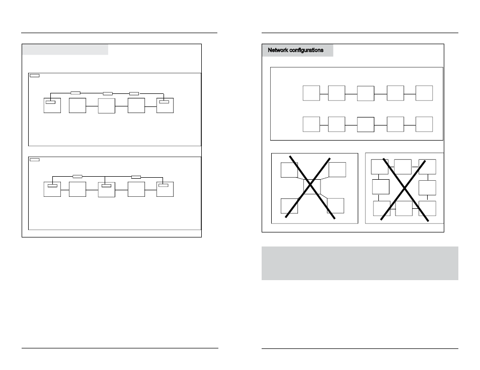
5X00 networks must be configured point to point (instrument to instrument).
Network wiring cannot contain loops, stars, or stubs - figure 3.30.
Installation and Wiring
Network configurations
Master
Master
Master
slave
slave
slave
slave
slave
slave
slave
slave
slave
slave
slave
slave
slave
slave
slave
do not wire “star” network
follow master/slave wiring directions figure 3.28
Master
slave
slave
slave
slave
do not wire “loop” network
b
b
good
good
bad
bad
Network configurations
Figure 3.30
Test Network Wiring and Configuration
Apply power to only the master and last slave device on the network. If the master is
not the first physical device on the network, apply power to the master and the first
and last physical slave devices on the network. See Network beginning on page 98.
Step 9 Wire and Install Communication Equipment
Communication equipment must be installed in order to communicate, either locally
or remotely, with the 5X00. The communication connection can be made locally
(RS232) or remotely with a serial to ethernet device. Only 1 connection method
can be used at a time. AquaManager supports both connection methods.
Installation and Wiring