Hardware installation, Step 1 install 5x00, Location considerations – YSI 5500D-1 User Manual
Page 14
YSI 5X00
27
YSI 5X00
26
Hardware Installation
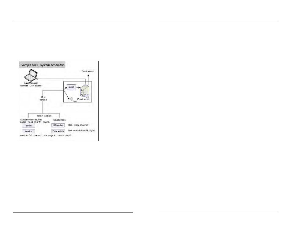
Correctly install 5X00 system components to ensure accurate data collection and
reliable operation. First, determine what monitor, control, and alarm functions
the 5X00 system will perform. Because system components are wired to the 5X00
instrument, it is important to determine where and how components will be installed
and configured. Preparing a system schematic (figure 3.1) is helpful.
Figure 3.1
Hardware installation steps (not all steps required for all applications):
Step 1 - install 5X00 instrument
Step 2 - locate and install sensor(s)
Step 3 - ground 5X00
Step 4 - wire power
Step 5 - wire sensors(s)
Step 6 - wire relays (output devices)
Step 7 - wire aux input devices (excluding temperature probes)
Step 8 - wire a network of 2 - 32 instruments
Step 9 - install and wire communication equipment
See Chapter 4 Configuring 5X00 Systems - starting on page 74 for directions on
programming 5X00 systems.
Tools and supplies needed for hardware installation:
•
Phillips-head screwdriver to remove 5X00 front panel to access I/O board
and lower board assembly
•
necessary tools for cutting mounting holes in mounting brackets (rail mount)
and/or control panel (panel mount)
•
5/32” Allen wrench (panel mount only)
•
electric drill and bits for mounting 5X00 (panel or rail) and for drilling rub-
ber grommets in bulkhead fittings
•
small flat-head screwdriver to terminate wires on I/O board pluggable
terminal strips
•
wrench to tighten bulkhead fittings following system component wiring
•
tweezers to replace the membrane gasket on the YSI 5422 sensor
•
wire strippers
•
distilled water for DO membrane installation
•
contactors may be required for relay wiring; see contactor wiring - page 58 .
Optional accessories for hardware installation:
•
surface mount hardware (included)
•
rail mount hardware
•
panel mount hardware
•
weather shield hardware
•
serial to ethernet device
•
wiring for network wiring
•
wiring not supplied with components and/or peripheral devices
Step 1 Install 5X00
Select a mounting location and method to mount the 5X00.
Location Considerations
The 5X00 must be located:
• above any level where water damage can occur
• away from extremely high or low temperature sources
• away from vibrating surfaces
• at least two 2 feet (~.7 m) from any high voltage conduit
•
away from electromagnetic, radio, AC motor, transformer, or antennas
• so the front panel can be fully opened and serviced
• so system component wires are run as specified in this manual and according
to local applicable electrical code
Installation and Wiring
Installation and Wiring