YSI 5500D-1 User Manual
Page 31
YSI 5X00
61
YSI 5X00
60
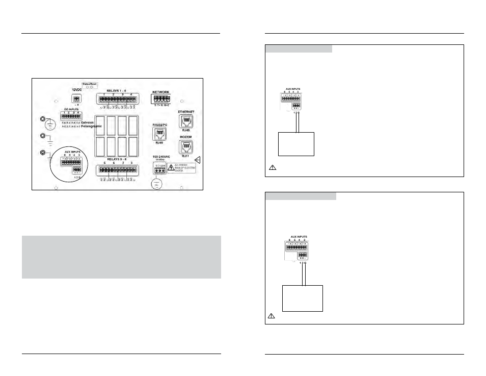
See Digital Input example - figure 3.24 and Analog Input example - figure 3.25.
CAUTION: The auxiliary inputs are not isolated. Devices connected must be
electrically isolated from ground and the water.
D
o not c
onnec
t or disc
onnec
t IDC r
ibbon cable
when 5400 is po
w
er
ed
. S
er
ious damage can oc
cur
.
Figure 3.23
5. Complete other wiring to 5X00.
6. Close front panel - page 43.
7. Test aux systems.
Test Auxiliary Input Devices
Apply power to 5X00. See Aux Setup - digital page 148 and analog (non tempera-
ture) page 150 for configuration information. Verify display, control, and/or alarm
functionality based on user defined configuration.
Wire Aux Digital Input
1. Install aux digital device according to manufacturer’s instructions.
2. Connect switch wires to Aux Input 1 - 6. Connect ground wire to (G) at
location M
for aux 1 and 2 or to (-) at L
for aux 3, 4, 5, or 6. Connect the
other wire to (+) L
and to 1 or 2 at M
.
Instrument with
analog voltage
output
Auxiliary Input Connector
+ -
CAUTION: Do not input external voltage.
Figure 3.24
Wire Aux Analog Input
1. Install analog instrument according to manufacturer’s instructions.
2. Connect analog instrument wires to Aux Input 1 - 6. Connect ground wire to
the (G) at M for aux 1 and 2 or to (-) at L for aux 3, 4, 5, or 6. Connect the
other wire to 1 or 2 at M for aux 1 and 2 or to (+) at L for aux 3, 4, 5, or 6.
Instrument with
analog voltage
output
Auxiliary Input Connector
+ -
CAUTION: Observe correct polarity on analog input.
Figure 3.25
Installation and Wiring
Installation and Wiring