Step 5 wire sensor(s), Wire do sensors, Directions to wire do sensor(s) – YSI 5500D-1 User Manual
Page 26
YSI 5X00
51
YSI 5X00
50
Step 5 Wire Sensor(s)
Up to four DO sensors and four temperature sensors can be wired to the 5X00.
All sensors are wired to the I/O Board - figure 3.19 and 3.19a. Use location E or F
on metal plate to ground the DO sensor ground/drain wires. (Common lettering
references are used for both 5400 and 5500 models). Follow the wiring instructions
below to ensure proper sensor operation.
YSI probe assembly 5422 has one polarographic DO sensor and one temperature
sensor. YSI probe assembly 5421 has one galvanic DO sensor and one temperature
sensor. YSI probe assembly 5420 has one galvanic DO sensor. The probe assemblies
are shipped bare wire. YSI 5421 and 5422 probe assemblies have five wires. Two
wires are for the DO sensor and are terminated at location H on the I/O board.
Two wires are for the temperature sensor and are terminated at location L on the
I/O board. Terminate the fifth wire (ground/drain wire) to location E or F of metal
plate. The YSI 5420 probe assembly has three wires for the DO sensor and does not
include any temperature sensor wires.
ODO probe assemblies have five wires. Four ODO sensor wires are terminated at
location H. Terminate the fifth (ground/drain wire) to location E or F of metal plate.
Complete directions and wiring diagram are provided at step 4 (5500) - page 52.
The ODO probe is a digital device and includes a temperature sensor.
Wire DO Sensors
Directions to Wire DO Sensor(s)
WARNING: Disconnect external power to the unit before wiring.
1. Perform steps 1 - 4 of 5X00 installation.
2. Open front panel - page 42.
3. Feed DO cable through drilled hole in rubber grommet to location H. The
terminal strip is removable.
CAUTION: Run high and low voltage cables through separate bulkhead and
conduit.
4. Terminate the DO sensor wires for the DO1, DO2, DO3, and/or DO4
system(s). Wire the DO sensor cathode wire to (+) terminals and the DO
sensor anode wire to (-) terminals. Follow the coloring scheme described
below when wiring the DO sensor.
• YSI 5422 polarographic DO sensor wires are green and white.
-Terminate green wire to “A Polarographic”.
-Terminate white wire to “C Polarographic”.
-Terminate bare ground/drain wire to E or F on metal plate.
5400
5500
5400
Notes ground/drain wire termination:
- Install a ring (eyelet) or spade (fork) terminal onto the ground bare wire before
terminating ground wire to E or F.
- Multiple ODO ground/drain wires can be terminated to the same ground
location on the metal plate.
- Return screw at E or F over terminal connection of ground wire.
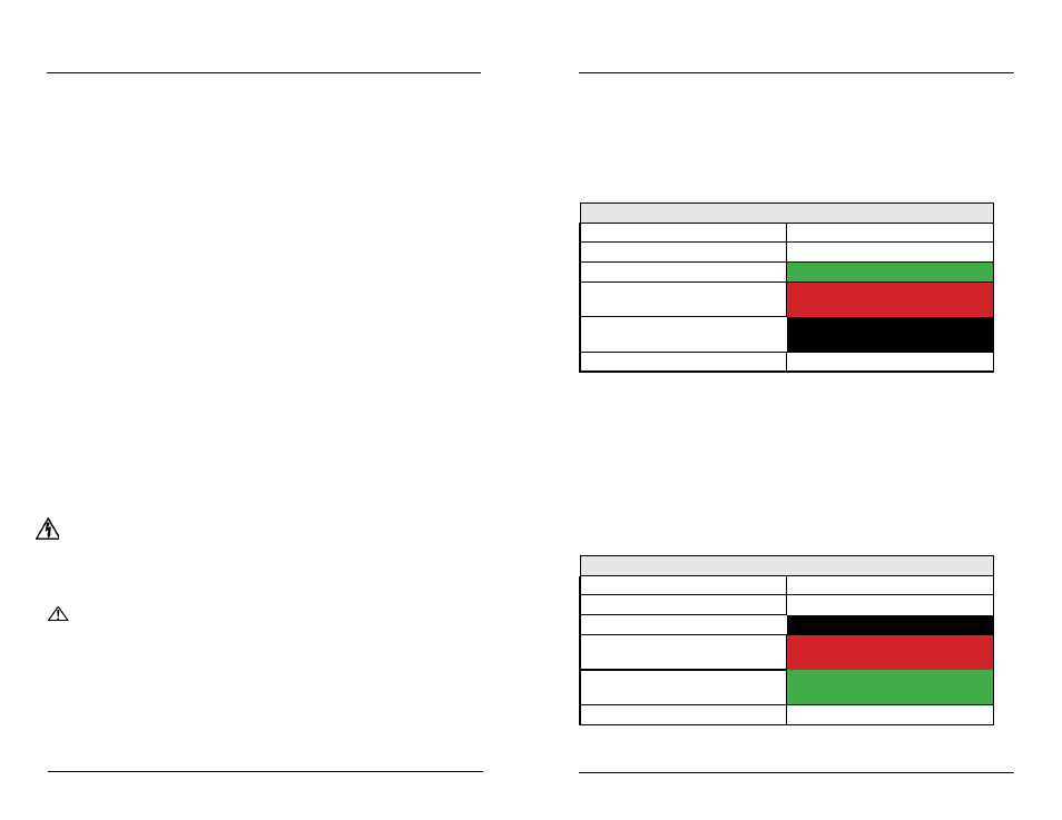
YSI 5422 polarographic DO/temperature analog sensor cable YSI
Wire Function
Wire label
Cathode (C) (+)
WHITE
Anode (A) (-)
GREEN
Temperature (
There is no polarity for
temperature sensor wires)
RED
Temperature (
There is no polarity for
temperature sensor wire)
BLACK
Ground/drain wire
BARE
• YSI 5420 & 5421 galvanic DO sensor wires are white and black.
-Terminate white wire to “C Galvanic”.
-Terminate black wire to “A Galvanic”.
-Terminate bare ground/drain wire to E or F on metal plate.
Notes ground/drain wire termination:
- Install a ring (eyelet) or spade (fork) terminal onto the ground bare wire before
terminating ground wire to E or F.
- Multiple ODO ground/drain wires can be terminated to the same ground
location on the metal plate.
- Return screw at E or F over terminal connection of ground wire.
YSI 5420 galvanic DO & 5421 galvanic DO/temperature analog sensor cable YSI
Wire Function
Wire label/color
Cathode (C) (+)
WHITE
Anode (A) (-)
BLACK
YSI 5421 Temperature (
There is no
polarity for temperature sensor wire)
RED
YSI 5421 Temperature (
There is no
polarity for temperature sensor wire)
GREEN
Ground/drain wire
BARE
Installation and Wiring
Installation and Wiring