Rectifiers – GE Industrial Solutions GPS 4848_100 Users Guide (dual rectifier shelf) User Manual
Page 66
Galaxy Power System 4848/100 with Dual Rectifier Shelf
9 - 4 Specifications
Issue 5 September 2011
Rectifiers
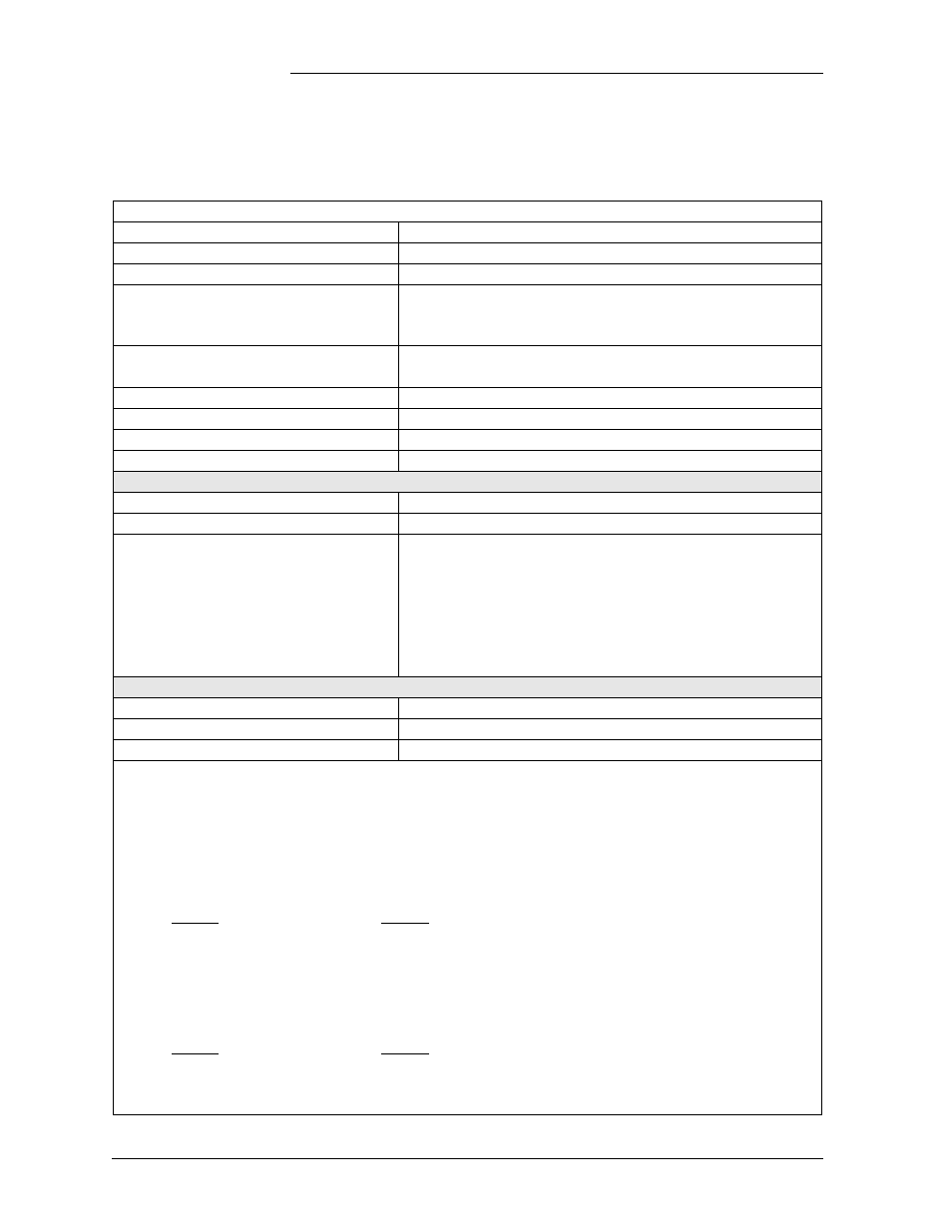
Table 9-B: 595LT Series S2:x Rectifier Specifications
Electrical
Output Voltage
52Vdc typical
Output Voltage Adjustment
44-58Vdc float/boost
Regulation (with controller)
±0.5%
Output Current
595LTA
595LTB
220A
0°C to 40°C
0°C to 37°C
At 50°C
200A
200A
High Voltage Shutdown
(selected by controller)
Float/boost 44-60Vdc (56Vdc default)
Backup High Voltage Shutdown
Float/boost 59-60Vdc (59.5Vdc nominal)
Output AC Ripple
100mVrms
Output Noise - Voiceband
55dBrnC
Current Limit Set Point
60Adc - 220Adc
595LTA Rectifier
595LTB Rectifier
Nominal Input Voltage (3-wire plus ground)
380 - 480 Vac
200 - 240 Vac
Input Voltage Range (per phase)
320 - 530 Vac
176 - 275Vac
Input Current
Specified
Rated Maximum
Typical Maximum
20A at 480Vac
40A at 208Vac
25A at 380Vac
35A at 240Vac
30A
50A
22A at 320Vac
41A at 176Vac
19A at 380Vac
36A at 200Vac
15A at 480Vac
33A at 208Vac
30A at 240Vac
Frequency Range
47 - 63 Hz
Power Factor
0.99 from 50% to 100% load
Total Harmonic Distortion
<5% from 50% to 100% load
AC Surge Protection: It is important that ac surges reaching rectifiers do not exceed the capacity of the rectifier
internal surge protection. Protection must be provided external to the GPS system to limit surge energy reaching
the rectifiers. Site surge protection must be coordinated with rectifier internal surge protection and must clamp at
a lower voltage than the rectifier internal protection. The internal protection voltage and current characteristics of
the rectifiers are as follows:
595LTA
Phase to Phase
MOV Conduction
Voltage
Current
625 Vac (RMS)
0 A
940 Vpeak
1 mA
1650 Vpeak
100 A
595LTB
Phase to Phase
MOV Conduction
Voltage
Current
320 Vac (RMS)
0 A
462 Vpeak
1 mA
810 Vpeak
100 A