OSRAM QUICKTRONIC INTELLIGENT DIM CFL User Manual
Page 19
18
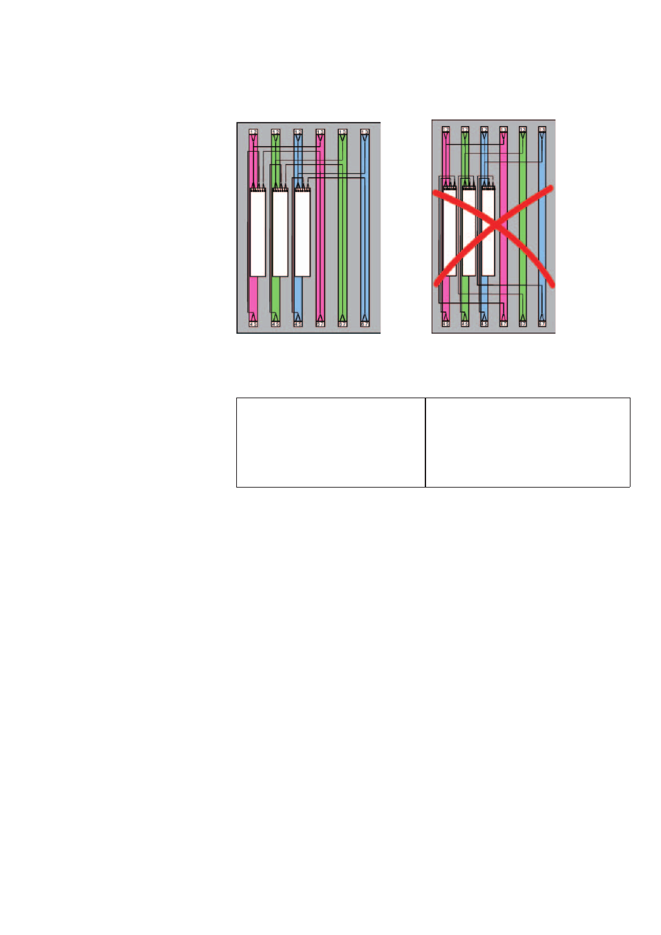
Figure 7: Three 2-lamp ECGs
Correct: Wrong:
The lamp lines are laid close
to the respective lamps. The
overlapping of the three right
lamp current circuits is mini-
mized.
The lamp lines of all ECGs are laid
together, also overlapping lamp
current circuits are formed in this
way.
Note:
T5 florescent lamps must be used so that the lamp stamps are on
the same side. The lamp stamp must be underneath (Cold Spot) in
the upright burning position. If this is not the case, the lamp param-
eters will fluctuate which can lead to unstable burning behavior of the
lamp.
2.5
The DALI interface – technical details
DALI defines the digital communication between a control unit with
DALI interface and a DALI controller (ECG). The detailed specifications
of the DALI interface can be found in IEC 62386.
2.5.1 The DALI system principle
Each control unit works as a "master" and controls communication on
the control cable. ECGs, in contrast, may only respond as a "slave" to
a request of the "master".
DALI relies on consistent intelligence distributed throughout the
system, an intelligent control unit communicates with intelligent com-
ponents. For example, the control unit only issues the command:
"Scene 1" and the processor in the ECG adopts the desired light
value. This way all ECGs achieve the set value at the same time.