Table 53 - indicator led debug answers – B&B Electronics WLNN-EK-DP551 - User Manual User Manual
Page 55
B&B Electronics
Airborne Enterprise WLNN EVB Users Guide
55
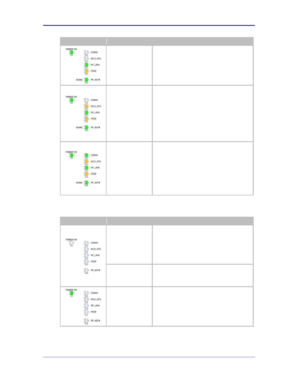
LED Configuration
State
Description
Device Server has
Authenticated with a
wireless network
When the RF_LINK LED is on the Airborne Device
Server module is associated to a wireless network. If
DHCP is enabled the module will request an IP
address, subnet, gateway and DNS server addresses.
Device Server
configured for network
communication
The WLN_CFG LED ON indicates the Airborne Device
Server module has installed a valid IP address and is
available for network communication.
It may take several seconds for the WLN_CFG LED to
turn ON after the RF_LINK LED is ON, this delay is due
to the DHCP lease process.
If static IP addressing is being used the WLN_CFG LED
will turn ON after network services are available on the
module. This will be a few seconds after POST has
turned ON.
TCP/IP connection has
been established with
the Airborne Device
Server Module
The COMM LED turning ON indicates that a TCP/IP
connection has been established between the Device
Server and a network device. This connection could be
a web interface, CLI interface or a data tunnel
connection.
The COMM LED will turn ON whether the TCP/IP
connection has been initiated by the Device Server or
from the network. If initiated from the Device Server
this indicates a successful connection with the target
Server has been made.
TABLE 53 - INDICATOR LED DEBUG ANSWERS
LED Configuration
Issue
Description
Plugged in the power
supply and turned on
SW1 and D3 does not
turn ON
Check the outlet plugged into is powered. Try a second
outlet.
Check the Airborne power supply is connected
correctly, reseat the power cable to the power brick.
Check that JP1 is configured to use the external power
supply.
Populated BT1 with 4 x
AA cells and turned on
SW1 and D3 does not
turn ON
Check that JP1 is configured to use batteries.
Make sure D2 is not ON. If D2 is ON replace the
batteries.
Power is applied but
after 10-12 seconds
RF_ACT# or POST do
not turn ON
Make sure the Device Server Module (Ref Figure 1) is
attached to the Evaluation board. Confirm the module
is seated correctly by pushing lightly down on the units
using the edges of the device. Avoid pushing on the
label.