Led4, Table 39 - led4 description, Figure 17 - sw1 set-up – B&B Electronics WLNN-EK-DP551 - User Manual User Manual
Page 32: 29 led4, 30 sw1, 31 sw2
B&B Electronics
32
Airborne Enterprise WLNN EVB Users Guide
Group
Designator
Name
Description (w/ Power Applied)
D12
POST
(Yellow)
OFF
Passed Power-on-Self-Test
ON
Failed Power-on-Self-Test
A more detailed description of these status indicators can be seen in section
13.0.
5.29 LED4
This group of LED
’s is available for use. They can be connected to and driven by
GPIO G0 and G1, via the CLI of the Airborne Device Server module. It is possible
to demonstrate I/O control using this combination.
They can be connected to the GO and G1 ports via J10 (section 5.23). Please
refer to this section for more details.
TABLE 39 - LED4 DESCRIPTION
Group
Designator
Description
LED4
D17
G1 (Yellow LED)
D16
G0 (Yellow LED)
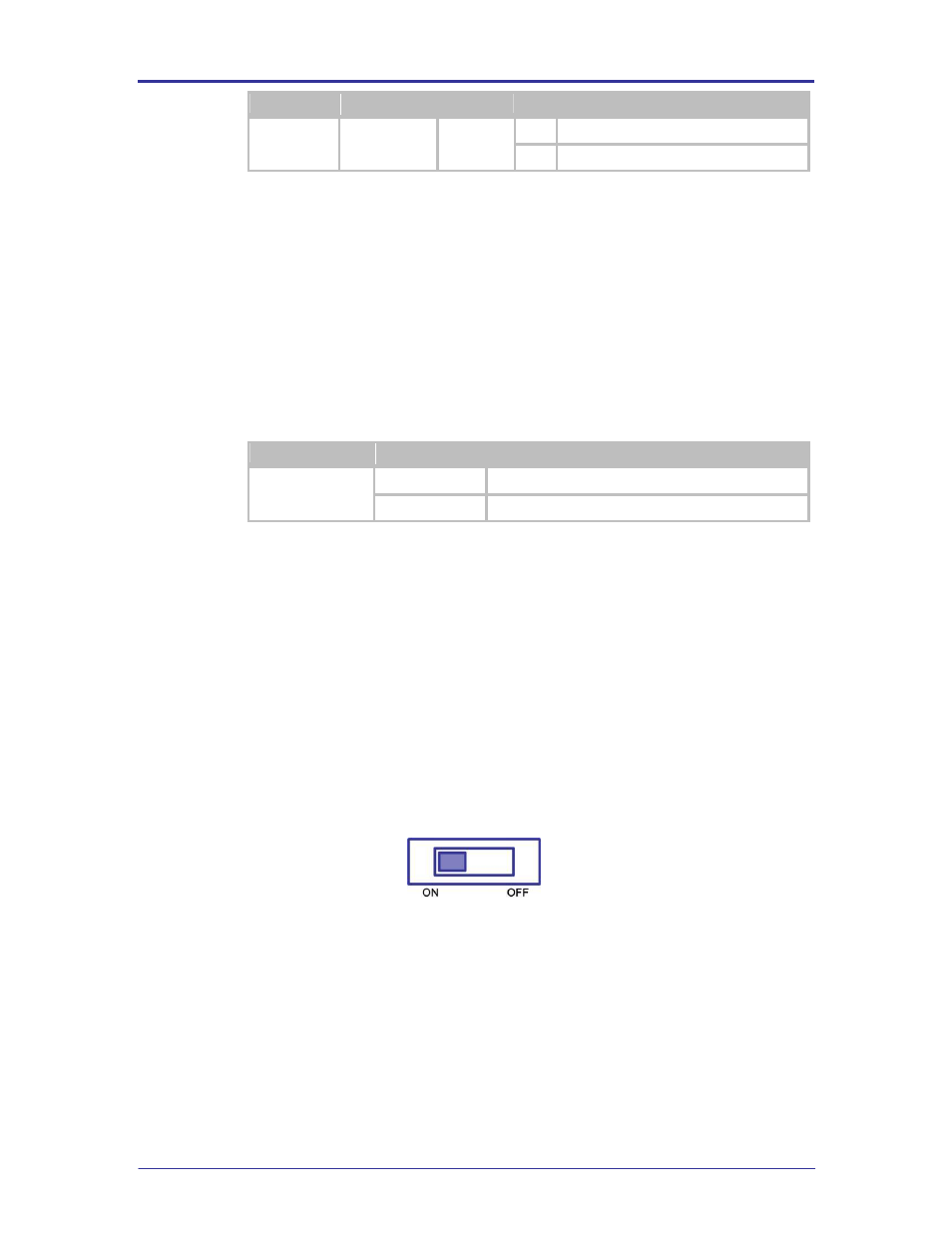
5.30 SW1
This is the main power switch for the evaluation board. A valid power supply
(included with kit) must be connected to J1 and JP1 must be configured for an
external power supply (default set-up) or BT1 must have a valid set of cells and
JP1 must be configured for Batteries before the switch is enabled.
If a valid power source is attached, D3 (section 5.12) will light. This will indicate
the start of the Airborne Device Server boot cycle. The cycle may take several
seconds; please allow enough time to complete the boot cycle before resetting
the switch.
When the Airborne Device Server boot successfully you will see the POST
(section 5.28) and RF_ACT LED (section 5.28) indicators light.
FIGURE 17 - SW1 SET-UP
5.31 SW2
This push button switch restarts or reboots the Airborne Device Server module. If
pressed for more than 100ms the module will initiate an internal power-on restart
cycle. This switch is connected to pin 7 (/RESET) pin of the module; please refer
to the W LNN DP500 Data-book for more details.
The /RESET behavior is not the same as a Power-on-restart; please refer to the
WLNN DP500 Data-book for details.