Figure 9 - de-9 connector pin-out, 18 j5 – B&B Electronics WLNN-EK-DP551 - User Manual User Manual
Page 24
B&B Electronics
24
Airborne Enterprise WLNN EVB Users Guide
5.18 J5
This header configures the Secondary UART port connector (CN2), selection of
the headers allows the connector pin-out to be changed to support one of the
following configurations:
RS232 DTE
RS232 DCE
RS422/485 4-wire
RS422/485 2-wire
For each of the configurations please note there is a pin out change and it may
be necessary to alter the cable being used for connection to the serial host. The
different configurations of jumpers and pin outs can be seen in Table 22.
It is not possible to independently select the transceiver type for each UART port
(CN1 and CN2) consequently both ports must be the same type (RS232 or
RS422/485).
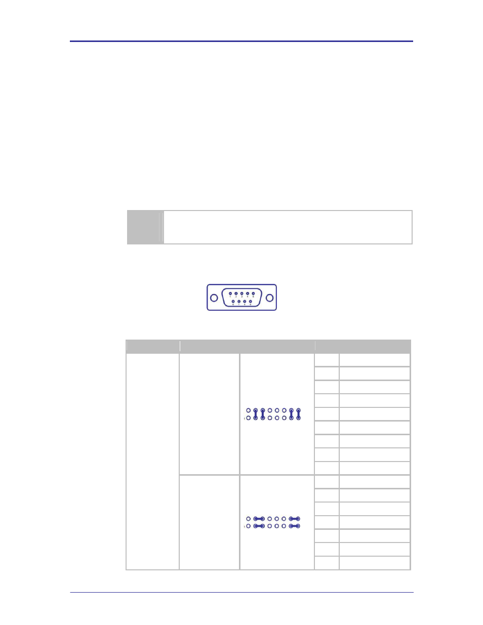
FIGURE 9 - DE-9 CONNECTOR PIN-OUT
TABLE 22 - SECONDARY UART PIN-OUT HEADER CONFIGURATION
Designator
Configuration
Header
Pin Out
J5
RS232 DTE
(Default)
1
No Connect
2
RxD
3
TxD
4
No Connect
5
GND
6
No Connect
7
RTS
8
CTS
9
No Connect
RS232 DCE
1
No Connect
2
TxD
3
RxD
4
No Connect
5
GND
6
No Connect
7
CTS