Figure 14 - gpio led header, 23 j10, 24 j11 – B&B Electronics WLNN-EK-DP551 - User Manual User Manual
Page 29
B&B Electronics
Airborne Enterprise WLNN EVB Users Guide
29
TABLE 29 - AIRBORNE DEVICE SERVER MODULE STATUS INDICATOR HEADER PIN-OUT
Designator
Pin
Description
J9
1
D12 (POST LED)
2
LED_POST (Airborne Device Server Module)
3
D13 (RF_LINK LED)
4
LED_RF_LINK (Airborne Device Server Module)
5
D14 (WLN_CFG LED)
6
LED_CFG_WLN (Airborne Device Server Module)
7
D15 (CONN LED)
8
LED_CON (Airborne Device Server Module)
Signals on Pins 2, 4, 6 and 8 are sourced directly from the Airborne Device Server
module and are not buffered or driven by the Evaluation board.
5.23 J10
This header allows GPIO pins sourced from the Airborne Device Server module
to be connected to LED
’s on the Evaluation board. These indicators can be used
to demonstrate control of the G0 and G1 ports via the CLI or web interface.
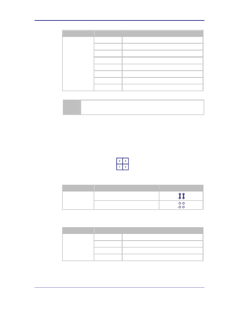
FIGURE 14 - GPIO LED HEADER
TABLE 30 - GPIO LED HEADER CONFIGURATION
Designator
Description
Configuration
J10
LED’s Connected
LED’s Disconnected
TABLE 31 - GPIO LED HEADER PIN-OUT
Designator
Pin
Description
J10
1
D16 (Yellow)
2
Port G0 (Airborne Device Server Pin 22)
3
D17 (Yellow)
4
Port G1 (Airborne Device Server Pin 19)
5.24 J11
This header connects the Airborne Device Server module sources indicator
signals to the Ethernet jack. A description of the signals can be seen in section
5.7.