4 cn1, 5 cn2, 6 cn3 – B&B Electronics WLNN-EK-DP551 - User Manual User Manual
Page 15
B&B Electronics
Airborne Enterprise WLNN EVB Users Guide
15
5.4
CN1
This is the primary UART port and should be used for serial communication with
the card during initial evaluation. The pin out for the connector is managed by the
configuration of J2; it can support the following modes:
RS232 DTE
RS232 DCE
RS422/485 4-wire
RS422/485 2-wire
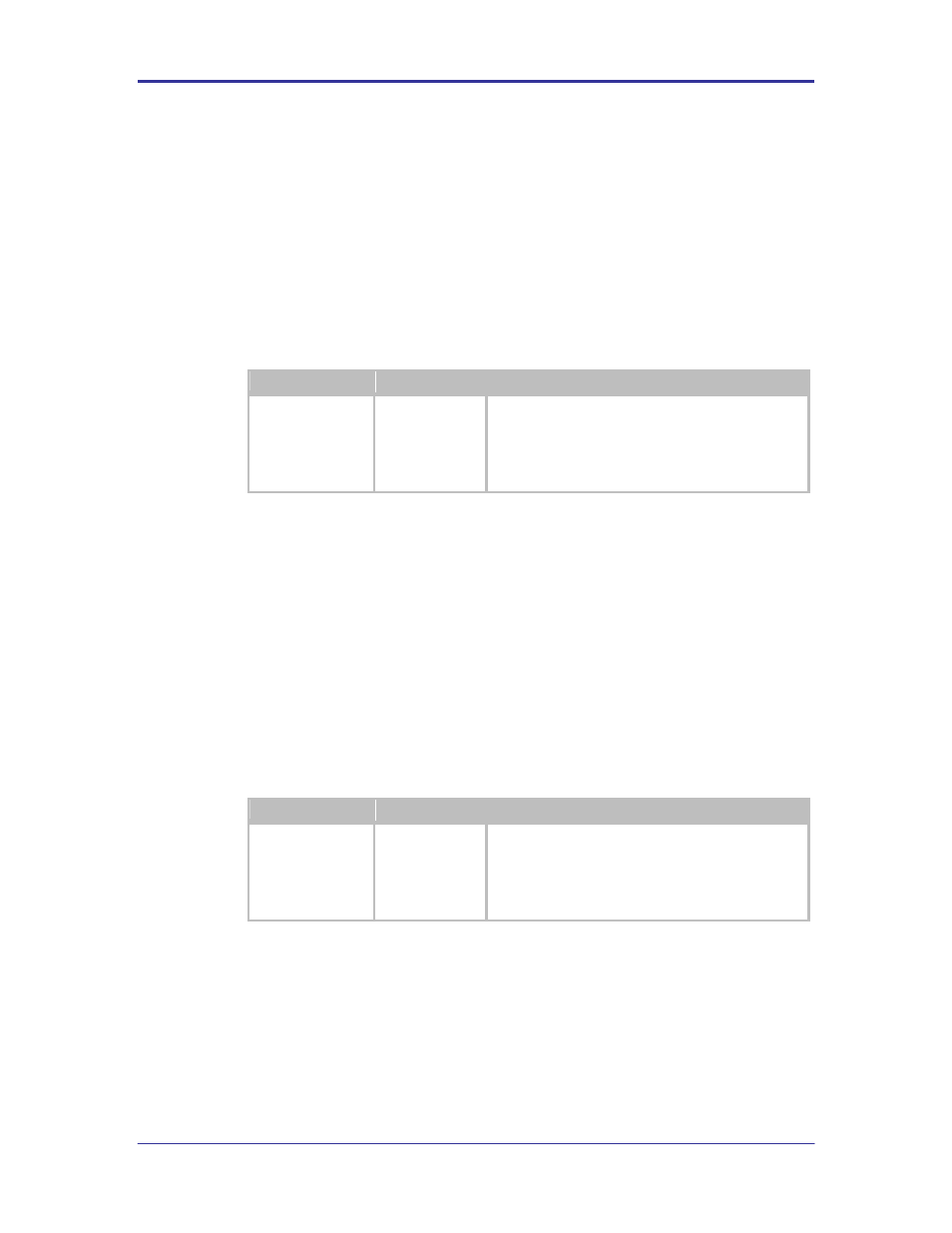
TABLE 5 - PRIMARY UART CONNECTOR
Designator
Connector
Description
CN1
DE-9 Male
Requires a DE-9 female connector. Depending upon
the configuration of J1 the following cable type should
be used:
DTE (Default):
Straight through
DCE:
Null Modem
5.5
CN2
This is the secondary UART port. This port can only be used if enabled via
firmware.
The pin out for the connector is managed by the configuration of J5; it can
support the following modes:
RS232 DTE
RS232 DCE
RS422/485 4-wire
RS422/485 2-wire
TABLE 6 - PRIMARY UART CONNECTOR
Designator
Connector
Description
CN2
DE-9 Male
Requires a DE-9 Female connector. Depending upon
the configuration of J5 the following cable type should
be used:
DTE (Default):
Straight through
DCE:
Null Modem
5.6
CN3
This header provides direct connections to the Airborne Device Server module
Ethernet connections. The output of this header is provided by the embedded
Ethernet PHY built in to the Airborne Device Server module. Please refer to the
WLNN DP500 data book for details of this output.
This header allow for the implementation of external magnetic or a capacitive
coupled circuit between the Evaluation board and a test system. The pin out for
the header can be seen in Table 7.