Figure 12 - secondary uart led indicator header – B&B Electronics WLNN-EK-DP551 - User Manual User Manual
Page 27
B&B Electronics
Airborne Enterprise WLNN EVB Users Guide
27
Signal RXEN (Pin 2), SER_MODE (Pin 6) and /TXEN (Pin 8) are sourced from the
Airborne Device Server module, please refer to the WLNN DP500 data book for a
description of these signal.
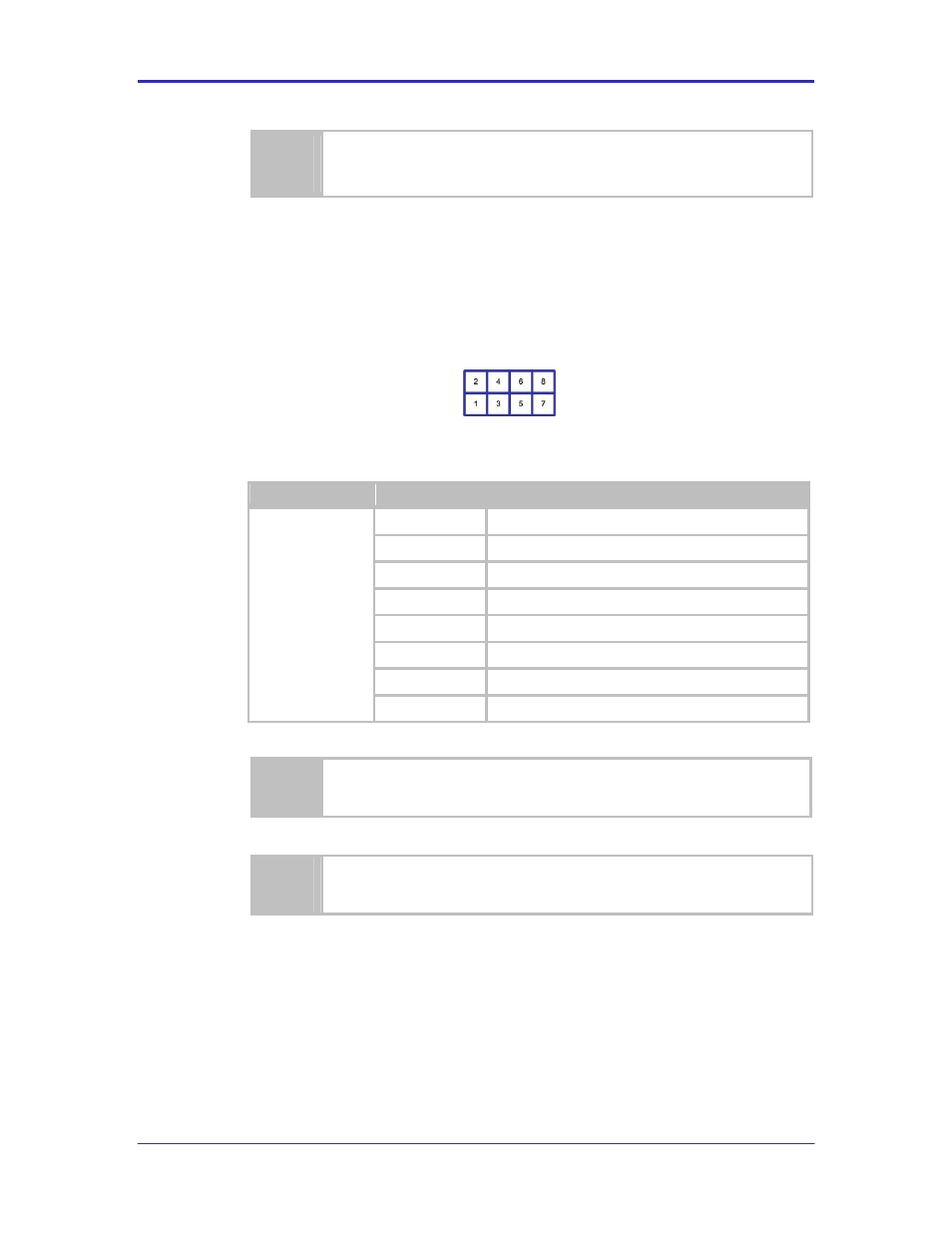
5.20 J7
This header provides access to the Secondary UART LED status indicators.
The default has all LED
’s connected.
FIGURE 12 - SECONDARY UART LED INDICATOR HEADER
TABLE 26 - SECONDARY UART LED INDICATOR HEADER PIN-OUT
Designator
Pin
Description
J4
1
RxD (EVB Signal Driver), D4 (Red LED)
2
RxD (Airborne Device Server Module)
3
TxD (EVB Signal Driver), D5 (Red LED)
4
TxD (Airborne Device Server Module)
5
CTS (EVB Signal Driver), D6 (Yellow LED)
6
CTS (Airborne Device Server Module)
7
RTS (EVB Signal Driver), D7 (Green LED)
8
RTS (Airborne Device Server Module)
Removing the jumpers from this header will disconnect the signals to the Secondary
UART connector CN2.
Signals on Pins 1, 3, 5 and 7 are sourced directly from the Airborne Device Server
module and are not buffered or driven by the Evaluation board.
5.21 J8
This header controls the access to the Ethernet interface. The options available
for this header can be seen in Table 27.