25 jp1 – B&B Electronics WLNN-EK-DP551 - User Manual User Manual
Page 30
B&B Electronics
30
Airborne Enterprise WLNN EVB Users Guide
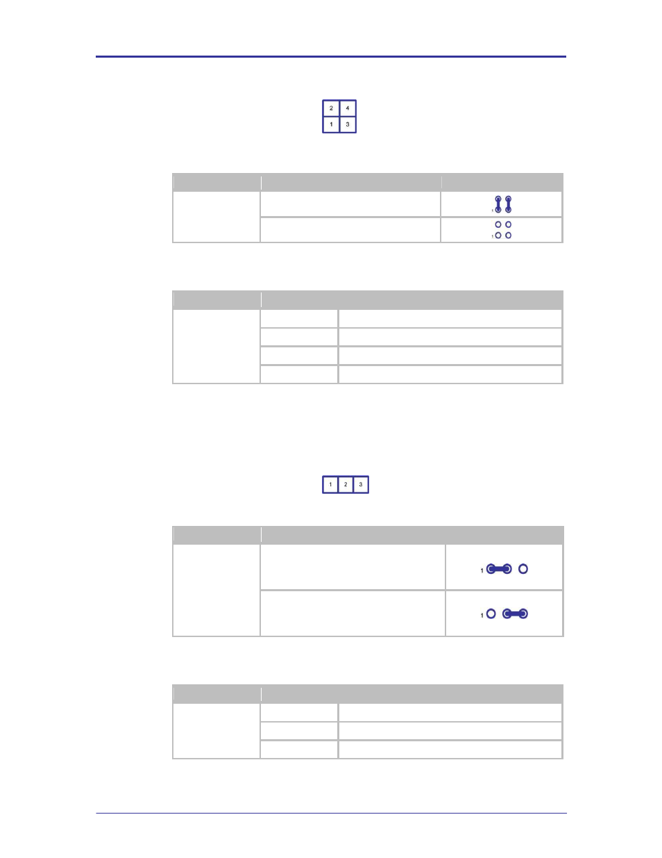
FIGURE 15 – ETHERNET INDICATOR LED HEADER
TABLE 32 – ETHERNET INDICATOR LED HEADER CONFIGURATION
Designator
Description
Configuration
J11
LED’s Connected (Default)
LED’s Disconnected
TABLE 33 – ETHERNET INDICATOR LED HEADER PIN-OUT
Designator
Pin
Description
J11
1
CN4 (Green LED)
2
LED_CON (Airborne Device Server Pin 23)
3
CN4 (Yellow LED)
4
Port F0 (Airborne Device Server Pin 25)
5.25 JP1
This jumper provides the ability to select the power source for the Evaluation
Board. The options can be seen in Table 34.
FIGURE 16 - JP1 PIN-OUT
TABLE 34 - POWER SOURCE SELECTOR
Designator
Description
Configuration
JP1
External power Supply.
This selects J1 (5.14) as the source for
power.
Battery power.
This selects BT1 (5.3) as the source for
power.
TABLE 35 - JP1 POWER SELECTOR PIN-OUT
Group
Pin
Description
JP1
1
J1 external 2.1mm Barrel jack.
2
EVB Power Supply Input
3
BT1 4 x AA cell holder
- USOPTL4DR-LS - Datasheet (2 pages)
- ZXT9-IOA-KIT - Manual (75 pages)
- ADAM-6066 - Manual (272 pages)
- 855-11619--57 - Datasheet (2 pages)
- 851-10904 - Datasheet (2 pages)
- SS-BLT-100PR - Quick Start Guide (1 page)
- ISOCON-6 - Datasheet (2 pages)
- I-7060 - Manual (64 pages)
- AMU864 - Datasheet (2 pages)
- 714FX6-SC_ST - Manual (154 pages)
- 422LP25R - Datasheet (2 pages)
- ZP9D-115RM-LR - Manual (54 pages)
- EKI-6311GN-EU - Manual (56 pages)
- ZZ24D-NA(NB,NC,ND)-SR - Quick Start Guide (4 pages)
- ESCLP-100 - Manual (23 pages)
- 806-39753 - Datasheet (1 page)
- 485SD9RJ - Datasheet (1 page)
- 712FX4-SC_ST - Manual (154 pages)
- 850-18610 - Manual (18 pages)
- ESW208 Series - Datasheet (2 pages)
- VESR321_ML_SL - Quick Start Guide (3 pages)
- OP10 - Datasheet (1 page)
- RT3G-300_310_320_330_340-W - Configuration Manual (79 pages)
- EIRHP305-T - Datasheet (2 pages)
- EIRSP1 - Datasheet (1 page)
- 422TTL33 - Datasheet (2 pages)
- 485DRCI - Quick Start Guide (2 pages)
- I-7021_P - Datasheet (2 pages)
- NTSA-CAT5E - Datasheet (2 pages)
- 485COSR - Datasheet (2 pages)
- 855-10619--57 - Datasheet (2 pages)
- UH401SL_2KV - Datasheet (2 pages)
- 105FXE-SC(ST)-15-POE - Manual (19 pages)
- 102MC-FL_SC_ST - Manual (23 pages)
- CBL00302 - Datasheet (1 page)
- 850-18100--27 - Datasheet (2 pages)
- 850-10953-DC - Datasheet (2 pages)
- ESR904 - Datasheet (2 pages)
- 308TX-N - Datasheet (3 pages)
- 422LP25N - Datasheet (2 pages)
- 708FX2-SC_ST - Datasheet (3 pages)
- MESR321_SL_ML - Datasheet (2 pages)
- SL2736-698 - Quick Start Guide (8 pages)
- I-7188E Series - Datasheet (1 page)
- ANT-PAD58-19 - Datasheet (1 page)