22 j9 – B&B Electronics WLNN-EK-DP551 - User Manual User Manual
Page 28
B&B Electronics
28
Airborne Enterprise WLNN EVB Users Guide
TABLE 27 - ETHERNET HEADER CONFIGURATION
Designator
Description
Configuration
J8
Ethernet Jack (Default)
CN3 Header
This header provides direct connections to the Airborne Device Server module
Ethernet connections. The output of this header is provided by the embedded
Ethernet PHY built in to the Airborne Device Server module. Please refer to the
WLNN DP500 data book for details of this output.
TABLE 28 - ETHERNET HEADER PIN-OUT
Designator
Pin
Description
J8
1
CN3 Pin 3
2
CN3 Pin 1
3
RxD+ (Airborne Device Server)
4
TxD+ (Airborne Device Server)
5
RxD+ (CN4)
6
TxD+ (CN4)
7
CN3 Pin 4
8
CN3 Pin 2
9
RxD- (Airborne Device Server)
10
TxD- (Airborne Device Server)
11
RxD- (CN4)
12
TxD- (CN4)
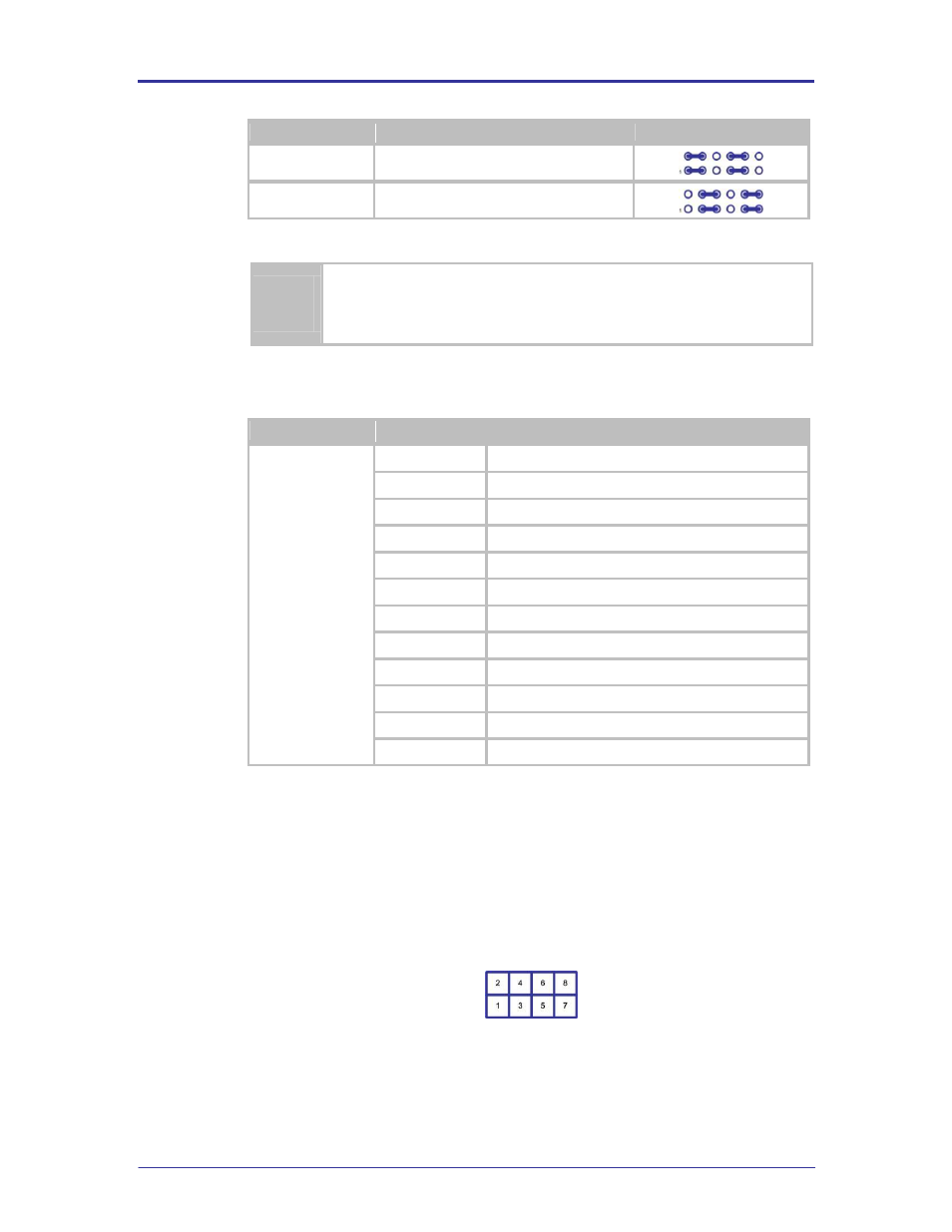
5.22 J9
This header provides access to the status indicators generated by the Airborne
Device Server module. The header provides a connection to the on board LED
’s
in the LED3 section 5.28.
The default has all LEDs connected.
FIGURE 13 – AIRBORNE DEVICE SERVER MODULE STATUS INDICATOR HEADER