Figure 3 - jtag header, 8 cn5, 9 cn6 – B&B Electronics WLNN-EK-DP551 - User Manual User Manual
Page 17
B&B Electronics
Airborne Enterprise WLNN EVB Users Guide
17
5.8
CN5
This connector provides access to the serial debug port available on the Airborne
Serial Device Server module. The debug/console port is supported by a 2-wire
serial interface defined in Table 10. This port is a bidirectional serial port intended
for debug of the unit only; it does not support data transfer.
TABLE 9 - DEBUG PORT CONNECTOR
Designator
Connector
Description
CN5
DE-9 Female
Requires a DE-9 Male connector. To connect to a
laptop or desktop serial port a straight thru cable is
required (included in kit).
The default settings for the debug port are 115200, 8, N 1, No Flow Control.
TABLE 10 - DEBUG PORT PIN OUT
Designator
Pin
Description
CN5
1
No Connect
2
D
OUT
3
D
IN
4
No Connect
5
GND
6
No Connect
7
No Connect
8
No Connect
9
No Connect
5.9
CN6
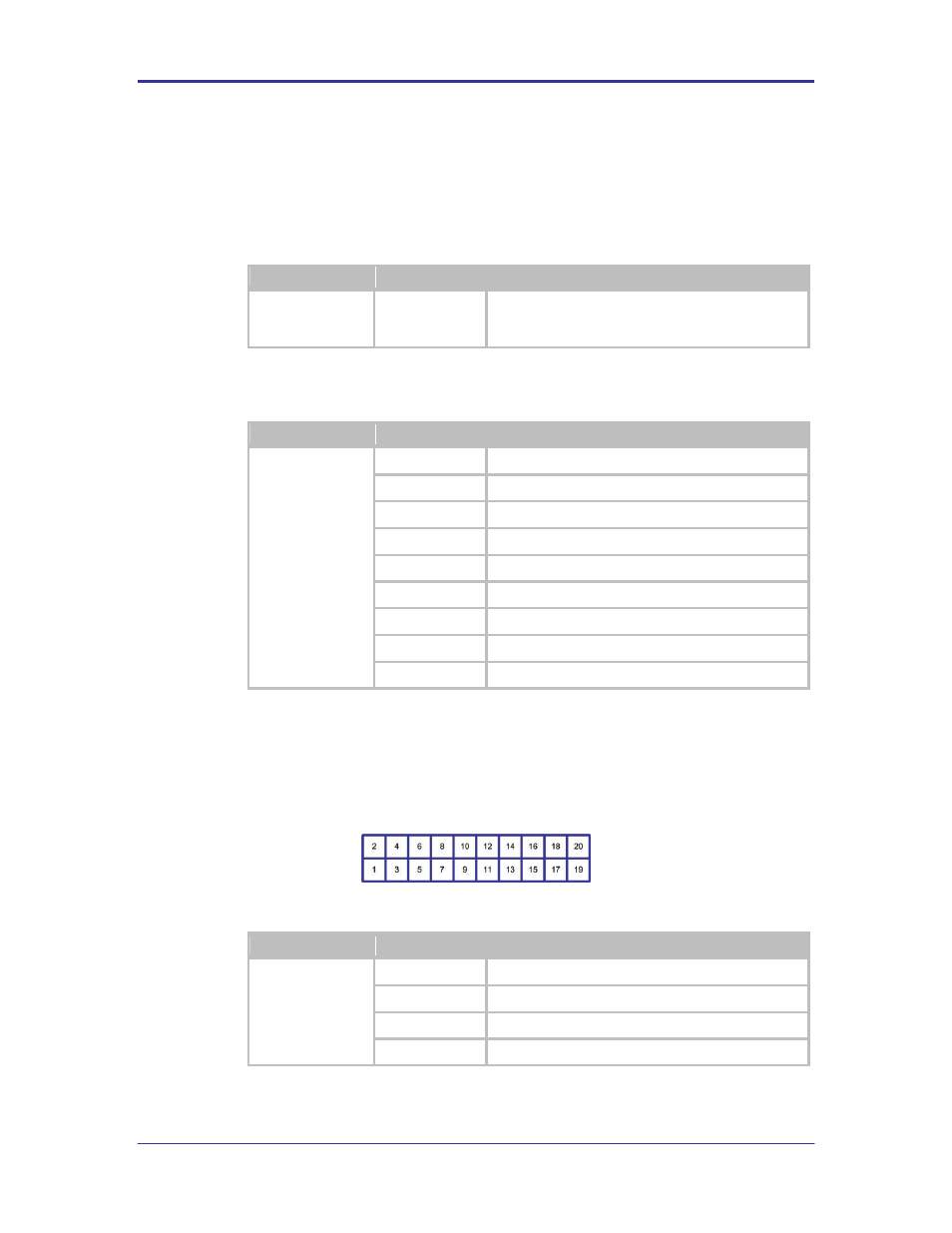
This header provides connectivity to the JTAG interface available on the Airborne
Device Server Module. The pin out for the header can be seen in Figure 3 and
Table 11.
FIGURE 3 - JTAG HEADER
TABLE 11 - JTAG HEADER PIN OUT
Designator
Pin
Description
CN6
1
3.3VDC
2
3.3VDC
3
NTRST: Test RESET
4
GND