Figure 8 - primary uart led indicator header, 17 j4 – B&B Electronics WLNN-EK-DP551 - User Manual User Manual
Page 23
B&B Electronics
Airborne Enterprise WLNN EVB Users Guide
23
Designator
Pin
Description
6
SER_MODE
7
RS422/485 Tx Enable (Active High)
8
/TXEN (Active Low)
Signal RXEN (Pin 2), SER_MODE (Pin 6) and /TXEN (Pin 8) are sourced from the
Airborne Device Server module, please refer to the WLNN DP500 data book for a
description of these signal.
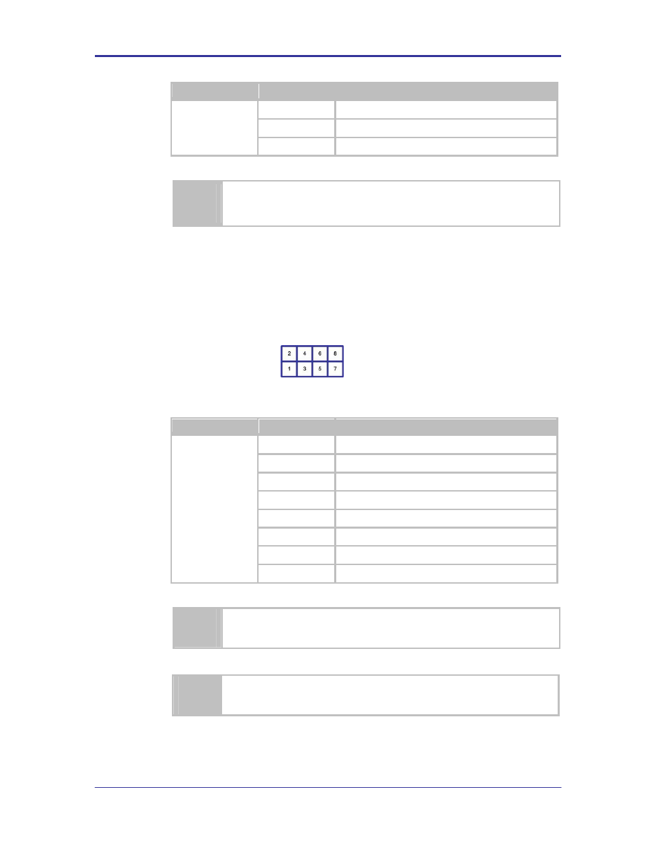
5.17 J4
This header provides access to the Primary UART LED status indicators.
The default has all LED
’s connected.
FIGURE 8 - PRIMARY UART LED INDICATOR HEADER
TABLE 21 - PRIMARY UART LED INDICATOR HEADER PIN-OUT
Designator
Pin
Description
J4
1
RxD (EVB Signal Driver), D4 (Red LED)
2
RxD (Airborne Device Server Module)
3
TxD (EVB Signal Driver), D5 (Red LED)
4
TxD (Airborne Device Server Module)
5
CTS (EVB Signal Driver), D6 (Yellow LED)
6
CTS (Airborne Device Server Module)
7
RTS (EVB Signal Driver), D7 (Green LED)
8
RTS (Airborne Device Server Module)
Removing the jumpers from this header will disconnect the signals to the Primary UART
connector CN1.
Signals on Pins 1, 3, 5 and 7 are sourced directly from the Airborne Device Server
module and are not buffered or driven by the Evaluation board.