Figure 2 - ethernet jack pin out, 7 cn4 – B&B Electronics WLNN-EK-DP551 - User Manual User Manual
Page 16
B&B Electronics
16
Airborne Enterprise WLNN EVB Users Guide
TABLE 7 - ETHERNET PHY HEADER PIN OUT
Designator
Pin
Description
CN3
1
TxD+
2
TxD-
3
RxD+
4
RxD-
A detailed description of the Ethernet circuit on the Evaluation board can be
found in section 11.0.
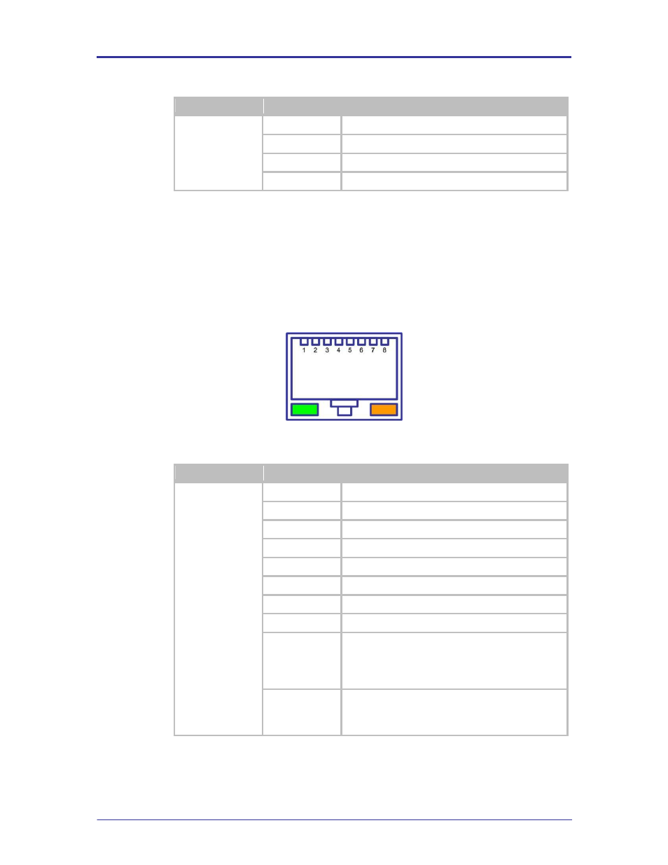
5.7
CN4
This connector is a 10/100 Ethernet RJ45 Jack with integrated magnetic. The pin
out is shown in Figure 2. It supports two integrated indicator LED
’s, the conditions
for these indicators can be seen in Table 8.
FIGURE 2 - ETHERNET JACK PIN OUT
TABLE 8 - ETHERNET CONNECTOR PIN OUT
Designator
Pin
Description
CN4
1
TxD+
2
TxD-
3
RxD+
4
NC
5
NC
6
RxD-
7
NC
8
NC
Green LED
Valid TCP/IP connection made with Airborne Device
Server:
Off
No TCP/IP connection
On
Valid TCP/IP Connection
Yellow LED
Power-on Self Test (POST):
Off
Not powered or has failed POST
On
Passed POST
- USOPTL4DR-LS - Datasheet (2 pages)
- ZXT9-IOA-KIT - Manual (75 pages)
- ADAM-6066 - Manual (272 pages)
- 855-11619--57 - Datasheet (2 pages)
- 851-10904 - Datasheet (2 pages)
- SS-BLT-100PR - Quick Start Guide (1 page)
- ISOCON-6 - Datasheet (2 pages)
- I-7060 - Manual (64 pages)
- AMU864 - Datasheet (2 pages)
- 714FX6-SC_ST - Manual (154 pages)
- 422LP25R - Datasheet (2 pages)
- ZP9D-115RM-LR - Manual (54 pages)
- EKI-6311GN-EU - Manual (56 pages)
- ZZ24D-NA(NB,NC,ND)-SR - Quick Start Guide (4 pages)
- ESCLP-100 - Manual (23 pages)
- 806-39753 - Datasheet (1 page)
- 485SD9RJ - Datasheet (1 page)
- 712FX4-SC_ST - Manual (154 pages)
- 850-18610 - Manual (18 pages)
- ESW208 Series - Datasheet (2 pages)
- VESR321_ML_SL - Quick Start Guide (3 pages)
- OP10 - Datasheet (1 page)
- RT3G-300_310_320_330_340-W - Configuration Manual (79 pages)
- EIRHP305-T - Datasheet (2 pages)
- EIRSP1 - Datasheet (1 page)
- 422TTL33 - Datasheet (2 pages)
- 485DRCI - Quick Start Guide (2 pages)
- I-7021_P - Datasheet (2 pages)
- NTSA-CAT5E - Datasheet (2 pages)
- 485COSR - Datasheet (2 pages)
- 855-10619--57 - Datasheet (2 pages)
- UH401SL_2KV - Datasheet (2 pages)
- 105FXE-SC(ST)-15-POE - Manual (19 pages)
- 102MC-FL_SC_ST - Manual (23 pages)
- CBL00302 - Datasheet (1 page)
- 850-18100--27 - Datasheet (2 pages)
- 850-10953-DC - Datasheet (2 pages)
- ESR904 - Datasheet (2 pages)
- 308TX-N - Datasheet (3 pages)
- 422LP25N - Datasheet (2 pages)
- 708FX2-SC_ST - Datasheet (3 pages)
- MESR321_SL_ML - Datasheet (2 pages)
- SL2736-698 - Quick Start Guide (8 pages)
- I-7188E Series - Datasheet (1 page)
- ANT-PAD58-19 - Datasheet (1 page)