11 d2, 12 d3, 13 d18 – B&B Electronics WLNN-EK-DP551 - User Manual User Manual
Page 19: 14 j1
B&B Electronics
Airborne Enterprise WLNN EVB Users Guide
19
Designator
Pin
Description
3
No Connect
4
No Connect
5
MISO: D
OUT
6
No Connect
7
SPI_CLK: SPI Clock
8
MOSI: D
IN
9
SPI_SEL: SPI Select
10
GND
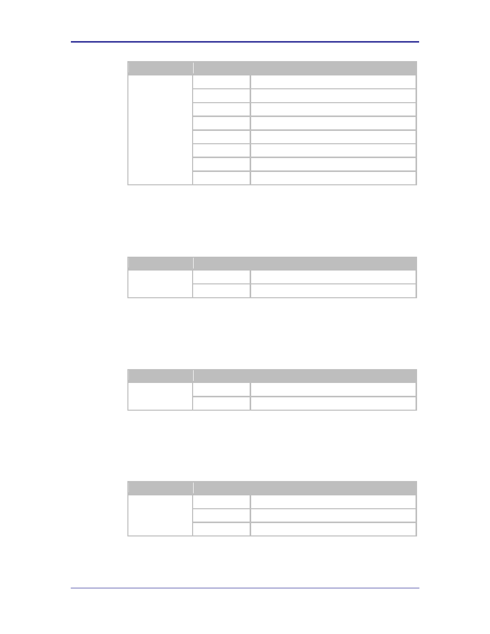
5.11 D2
This is a red indicator LED that provides feedback on the voltage level of the
power supply. This indicator will light when a low voltage state is detected.
TABLE 13 - LOW VOLTAGE LED INDICATOR
Designator
Status
Description
D2
ON
Power supply is 3.3VDC or less
OFF
Power supply is above minimum voltage
5.12 D3
This is a green indicator LED that provides feedback on the power status of the
Evaluation board.
TABLE 14 - POWER STATUS LED INDICATOR
Designator
Status
Description
D3
ON
Power supplied to the card, SW1 on ON position
OFF
No power supplied to the card, SW1 on OFF position
5.13 D18
This indicator LED provides feedback on the association status of the radio. The
indicator is provided by the RF_ACT output of the Airborne Device Server
module.
TABLE 15 - RF ACTIVITY LED INDICATOR
Designator
Status
Description
D18
OFF
No valid Power to the module
BLINKING
Searching for valid SSID
ON
Associated with valid SSID
5.14 J1
This is the main power jack for the Evaluation board. It requires a 5VDC/1.0A
minimum supply (supplied with kit).