Tp1 – 6, Table 40 - tp1-6 configuration, Figure 21 - tp7 layout – B&B Electronics WLNN-EK-DP551 - User Manual User Manual
Page 34: 34 tp1 – 6, 35 tp7
B&B Electronics
34
Airborne Enterprise WLNN EVB Users Guide
5.34 TP1
– 6
Included on the Evaluation board is a number of test points; these are available
for use by the user when evaluating or developing with the evaluation board. The
set of test points provide measurement or sourcing points for the various power
and ground options available on the board; Table 40 indicates the test point
function.
TABLE 40 - TP1-6 CONFIGURATION
Group
Designator
Description
Test Point
TP1
Input Voltage: This test point provides access to the
input voltage on J1.
TP2
3.3VDC: This test point provides access to the
regulated power supply output.
TP3
GND
TP4
GND
TP5
GND
TP6
GND
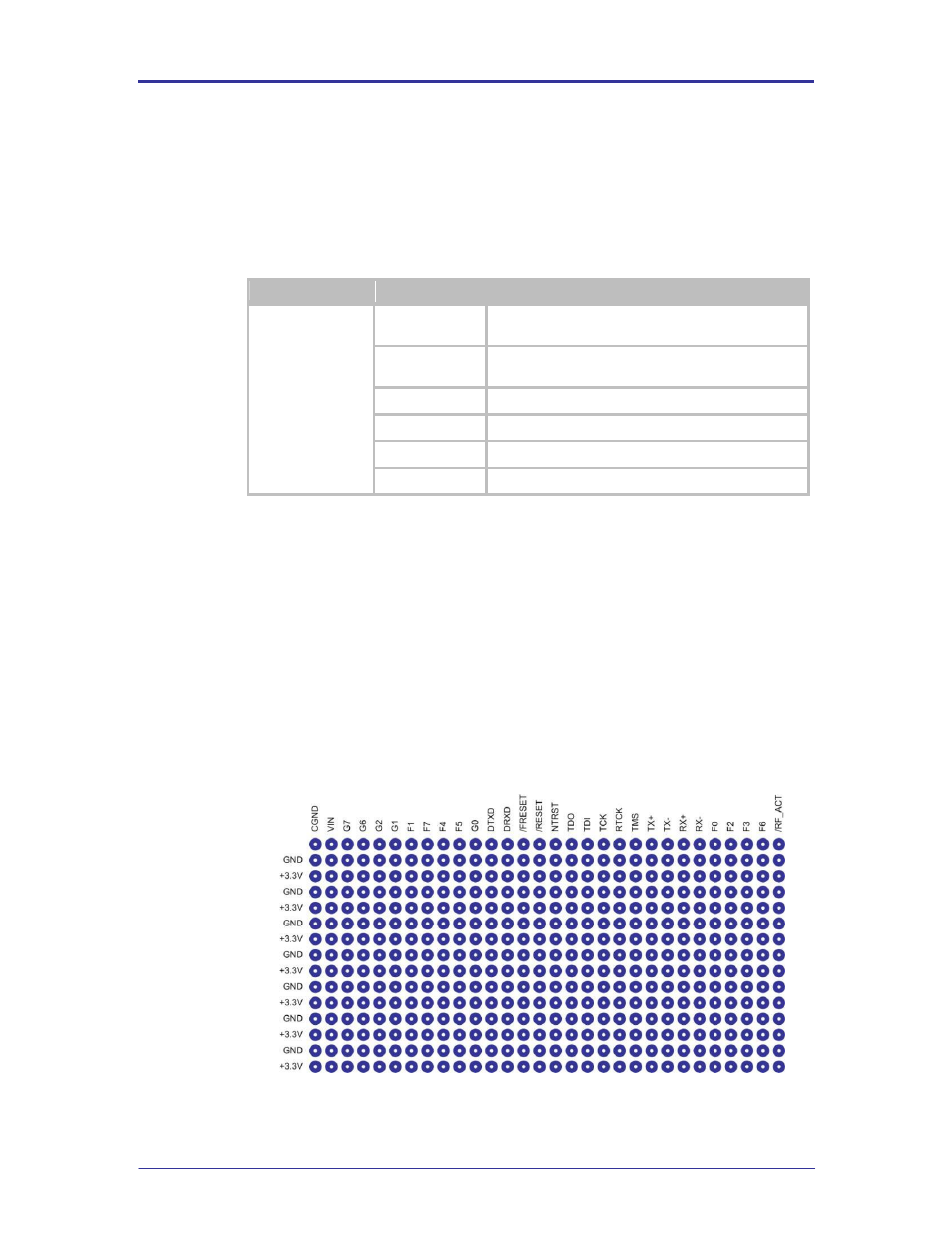
5.35 TP7
This section of the Evaluation board provides space for development of prototype
application hardware directly on the board. The matrix provides access to the full
interface of the Airborne Device Server module as well as an ample supply of
power and ground signals.
Since the signal definition could change depending upon the type of module
being used (UART, Serial, SPI, Ethernet) details of the signals and their
characteristics can be found in the W LNN DP500 Data book. A translation of
prototype area (TP7) designator to W LNN pin out can be seen in Table 41.
FIGURE 21 - TP7 LAYOUT