Rainbow Electronics DS2141A User Manual
Page 4
DS2141A
021997 4/35
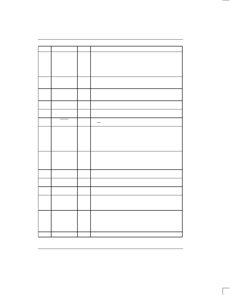
PIN
DESCRIPTION
TYPE
SYMBOL
25
RSYNC
I/O
Receive Sync. An extracted pulse, one RCLK wide, is output at this
pin which identifies either frame (RCR2.4=0) or multiframe bound-
aries (RCR2.4=1). If set to output frame boundaries, then via
RCR2.5, RSYNC can also be set to output double–wide pulses on
signaling frames. If the elastic store is enabled via the CCR1.2, then
this pin can be enabled to be an input via RCR2.3 at which a frame
boundary pulse is applied. See Section 13 for timing details.
26
27
RPOS
RNEG
I
Receive Bipolar Data Inputs. Sampled on falling edge of RCLK. Tie
together to receive NRZ data and disable bipolar violation monitoring
circuitry.
28
SYSCLK
I
System Clock. 1.544 MHz or 2.048 MHz clock. Only used when the
elastic store function is enabled via the CCR. Should be tied low in
applications that do not use the elastic store.
29
LI_SDI
O
Serial Port Data for the Line Interface. Connects directly to the SDI
input pin on the line interface.
30
LI_CLK
O
Serial Port Clock for the Line Interface. Connects directly to the
SCLK input pin on the line interface.
31
LI_CS
O
Serial Port Chip Select for the Line Interface. Connects directly to
the CS input pin on the line interface.
32
33
RCHBLK
TCHBLK
O
Receive/Transmit Channel Block. A user–programmable output
that can be forced high or low during any of the 24 T1 channels.
Useful for blocking clocks to a serial UART or LAPD controller in
application where not all T1 channels are used such as Fractional
T1, 384K bps service, 768K bps, or ISDN–PRI. Also useful for locat-
ing individual channels in drop–and–insert applications. See Section
13 for timing details.
34
RLOS/LOTC
O
Receive Loss of Sync/Loss of Transmit Clock. A dual function
output. If CCR1.6=0, then this pin will toggle high when the synchro-
nizer is searching for the T1 frame and multiframe. If CCR1.6=1,
then this pin will toggle high when the TCLK pin has not been toggled
for 5
µ
s.
35
INT2
O
Receive Alarm Interrupt 2. Flags host controller during conditions
defined in Status Register 2. Active low, open drain output.
36
INT1
O
Receive Alarm Interrupt 1. Flags host controller during alarm condi-
tions defined in Status Register 1. Active low, open drain output.
37
TLCLK
O
Transmit Link Clock. 4 KHz or 2 KHz (ZBTSI) demand clock for the
TLINK input. See Section 13 for timing details.
38
TLINK
I
Transmit Link Data. If enabled via TCR1.2, this pin will be sampled
during the F–bit time on the falling edge of TCLK for data insertion
into either the FDL stream (ESF) or the Fs–bit position (D4) or the
Z–bit position (ZBTSI). See Section 13 for timing details.
39
TSYNC
I/O
Transmit Sync. A pulse at this pin will establish either frame or mul-
tiframe boundaries for the DS2141A. Via TCR2.2, the DS2141A can
be programmed to output either a frame or multiframe pulse at this
pin. If this pin is set to output pulses at frame boundaries, it can also
be set via TCR2.4 to output double–wide pulses at signaling frames.
See Section 13 for timing details.
40
VDD
–
Positive Supply. 5.0 volts.