Rainbow Electronics DS2141A User Manual
Page 16
DS2141A
021997 16/35
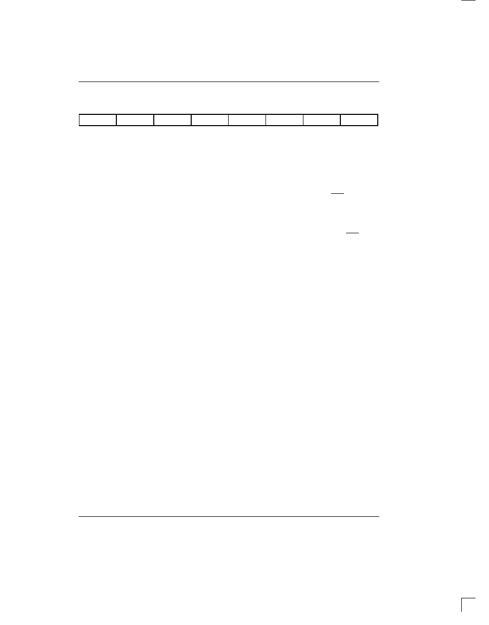
FECR: FRAME ERROR COUNT REGISTER (27h)
(MSB)
(LSB)
FE7
FE6
FE5
FE4
FE3
FE2
FE1
FE0
SYMBOL
POSITION
NAME AND DESCRIPTION
FE7
FECR.7
MSB of the Frame Error count.
FE0
FECR.0
LSB of the Frame Error count.
The Frame Error Count Register (FECR) is a 8–bit
counter that records either errors in the framing pattern.
The FECR will count individual bit errors in the ESF
framing pattern (...001011...) if the device is set into the
ESF framing mode (CCR2.3 = 1) and it will count individ-
ual bit errors in the Ft framing pattern (...101010...) in the
D4 framing mode (CCR2.3 = 0). If RCR2.1=1, then the
FECR will also record individual bit errors in the Fs fram-
ing pattern (...001110...) when it is in the D4 framing
mode. This counter saturates at 255 and will not roll
over. The counter is disabled during loss of sync condi-
tions.
6.0 FDL/FS EXTRACTION AND INSERTION
The DS2141A has the ability to extract/insert data from/
into the Facility Data Link (FDL) in the ESF framing
mode and from/into Fs–bit position in the D4 framing
mode. Since SLC–96 utilizes the Fs–bit position, this
capability can also be used in SLC–96 applications.
The operation of the receive and transmit sections will
be discussed separately.
6.1 Receive Section
In the receive section, the recovered FDL bits or Fs bits
are shifted bit–by–bit into the Receive FDL register
(RFDL). Since the RFDL is 8 bits in length, it will fill up
every 2 ms (8 x 250
µ
s). The DS2141A will signal an ex-
ternal microcontroller that the buffer has filled via the
SR2.4 bit. If enabled via IMR2.4, the INT2 pin will toggle
low indicating that the buffer has filled and needs to be
read. The user has 2 ms to read this data before it is lost.
If the byte in the RFDL matches either of the bytes pro-
grammed into the RFDLM1 or RFDLM2 registers, then
the SR2.2 bit will be set to a 1 and the INT2 pin will
toggled low if enabled via IMR2.2. This feature allows
an external microcontroller to ignore the FDL or Fs pat-
tern until an important event occurs.
The DS2141A also contains a zero destuffer which is
controlled via the CCR2.0 bit. In both ANSI T1.403 and
TR54016, communications on the FDL follow a subset
of a LAPD protocol. The LAPD protocol states that no
more than five 1s should be transmitted in a row so that
the data does not resemble an opening or closing flag
(01111110) or an abort signal (11111111). If enabled via
CCR2.0, the DS2141A will automatically look for five 1s
in a row, followed by a 0. If it finds such a pattern, it will
automatically remove the 0. If the 0 destuffer sees six or
more 1s in a row followed by a 0, the 0 is not removed.
The CCR2.0 bit should always be set to a 1 when the
DS2141A is extracting the FDL. More on how to use the
DS2141A in FDL applications is covered in a separate
Application Note.