0 introduction, Ds2141a block diagram – Rainbow Electronics DS2141A User Manual
Page 2
BPV COUNTER
SYNCHRONIZER
ALARM DETECTION
LOOP
CODE DETECT
OR
CRC/FRAME ERROR COUNT
ONE’S DENSITY
MONIT
OR
SIGNALING EXTRACTION
P
A
YLOAD LOOPBACK
TIMING CONTROL/
FDL EXTRACTION
ELASTIC
STORE
RECEIVE SIDE
FRAMER
RLOS
RLINK
RLCLK
RCHBLK
RCHCLK
RSER
SYSCLK
RSYNC
B8ZS DECODER
CHANNEL
MARKING
B8ZS ENCODE
YELLOW ALARM
GEN.
FDL
INSER
TION
CRC GEN.
F–BIT
INSER
TION
ONE’S DENSITY
ENCODER
LOOP
CODE GEN.
AIS GEN.
CLEAR CHANNEL
SIGNALING INSER
TION
IDLE CODE INSER
TION
TRANSMIT SIDE FORMATTER
ELASTIC
STORE
TSER
TIMING
CONTROL/
FDL
INSERT
TLINK
TLCLK
TSYNC
TCHCLK
TCHBLK
LOCAL
LOOPBACK
PARALLEL CONTROL PORT
(ROUTED TO ALL BLOCKS)
TCLK
LINE INTERFACE
CONTROL PORT
BTS
CS
WR(R/W)
RD(DS)
ALE(AS)
INT1/INT2
AD0–AD7
RPOS
RCLK
RNEG
TPOS
TNEG
LI_SDI
LI_SCLK
LI_CS
DS2141A
021997 2/35
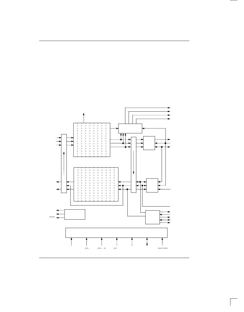
1.0 INTRODUCTION
The DS2141A T1 Controller has four main sections: the
receive side, the transmit side, the line interface control-
ler, and the parallel control port. See the block diagram
below. On the receive side, the device will clock in the
serial T1 stream via the RPOS and RNEG pins. The
synchronizer will locate the frame and multiframe pat-
terns and establish their respective positions. This in-
formation will be used by the rest of the receive side cir-
cuitry.
The DS2141A is an “off–line” framer, which means that
all of the T1 serial stream that goes into the device will
come out of it unchanged. Once the T1 data has been
framed to, the robbed–bit signaling data and FDL can be
extracted. The 2–frame elastic stores can either be en-
abled or bypassed.
The transmit side clocks in the unframed T1 stream at
TSER and adds in the framing pattern, the robbed–bit
signaling, and the FDL. The line interface control port
will update line interface devices that contain a serial
port. The parallel control port contains a multiplexed ad-
dress and data structure which can be connected to ei-
ther a microcontroller or microprocessor.
DS2141A BLOCK DIAGRAM