Rainbow Electronics DS2141A User Manual
Page 20
DS2141A
021997 20/35
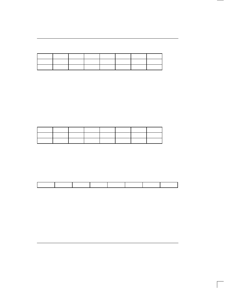
TTR1/TTR2/TTR3: TRANSMIT TRANSPARENCY REGISTERS (39h to 3Bh)
(MSB)
(LSB)
CH8
CH7
CH6
CH5
CH4
CH3
CH2
CH1
CH16
CH15
CH14
CH13
CH12
CH11
CH10
CH9
CH24
CH23
CH22
CH21
CH20
CH19
CH18
CH17
SYMBOL
POSITION
NAME AND DESCRIPTION
CH24
TTR3.7
Transmit Transparency Registers.
CH1
TTR1.0
0=this DS0 channel is not transparent.
1=this DS0 channel is transparent.
Each of the bit positions in the Transmit Transparency
Registers (TTR1/TTR2/TTR3) represents a DS0 chan-
nel in the outgoing frame. When these bits are set to a 1,
the corresponding channel is transparent (or clear). If a
DS0 is programmed to be clear, no robbed bit signaling
will be inserted nor will the channel have Bit 7 stuffing
performed. However, in the D4 framing mode, bit 2 will
be overwritten by a 0 when a Yellow Alarm is trans-
mitted.
TIR1/TIR2/TIR3: TRANSMIT IDLE REGISTERS (3Ch to 3Eh)
(MSB)
(LSB)
CH8
CH7
CH6
CH5
CH4
CH3
CH2
CH1
CH16
CH15
CH14
CH13
CH12
CH11
CH10
CH9
CH24
CH23
CH22
CH21
CH20
CH19
CH18
CH17
SYMBOL
POSITION
NAME AND DESCRIPTION
CH24
TIR3.7
Transmit Idle Registers.
0=do not insert the Idle Code into this DS0 channel.
CH1
TIR1.0
1=insert the Idle Code into this channel.
TIDR: TRANSMIT IDLE DEFINITION REGISTER (3Fh)
(MSB)
(LSB)
TIDR7
TIDR6
TIDR5
TIDR4
TIDR3
TIDR2
TIDR1
TIDR0
SYMBOL
POSITION
NAME AND DESCRIPTION
TIDR7
TIDR.7
MSB of the Idle Code.
TIDR0
TIDR.0
LSB of the Idle Code.
Each of the bit positions in the Transmit Idle Registers
(TIR1/TIR2/TIR3) represents a DS0 channel in the out-
going frame. When these bits are set to a 1, the corre-
sponding channel will transmit the Idle Code contained
in the Transmit Idle Definition Register (TIDR). Robbed
bit signaling and Bit 7 stuffing will occur over the pro-
grammed Idle Code unless the DS0 channel is made
transparent by the Transmit Transparency Registers.
TTR1 (39)
TTR2 (3A)
TTR3 (3B)
TIR1 (3C)
TIR2 (3D)
TIR3 (3E)