At83c26, Pad type description – Rainbow Electronics AT83C26 User Manual
Page 7
7
7511B–SCR–10/05
AT83C26
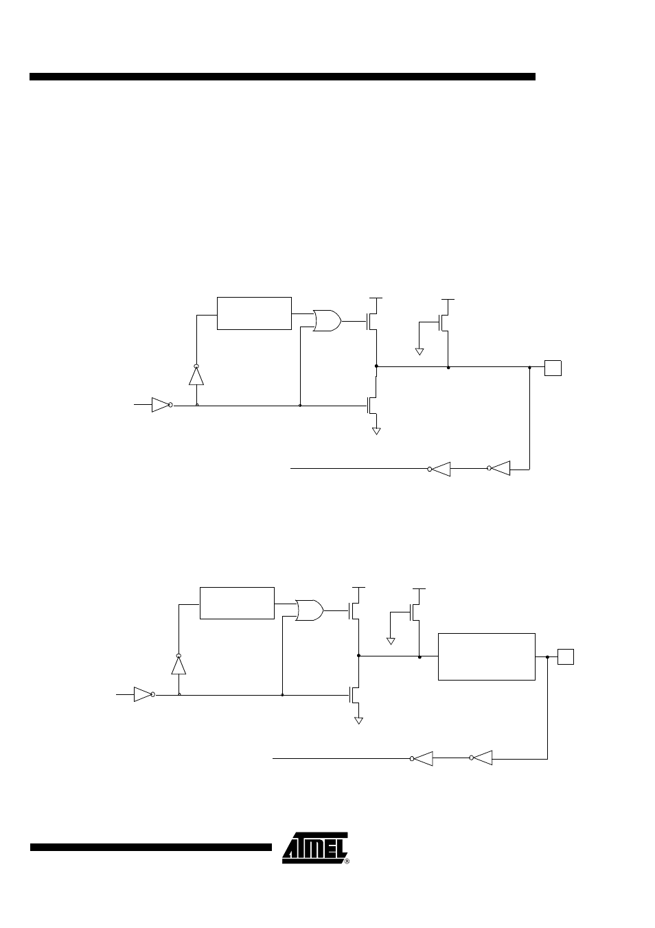
Pad Type Description
To simplify the understanding of Figure 1. to Figure 8., a shortcut is possible by replacing the
weak transistor by a 100k Ohms pull-up resistor, the medium transistor by a
10k Ohms pull-up resistor and the strong transistor by a 1k Ohms pull-up resistor.
Input/Output with Pull-up Configuration (IO1, IO2, AUX1, AUX2)
This output type can be used as both an input and output without the need to reconfigure the
port. This is possible because when the port outputs a logic high, it is weakly driven, allowing an
external device to pull the pin low. When the port outputs a logic low state, it is driven strongly
and able to sink a fairly large current.
Figure 1. Input/Output with Pull-up Configuration
Input/Output with Pull-up Configuration (CIOn with n = 1, 2, 3, 4, 5) and (CC4n, CC8n with n = 1,
2)
Figure 2. Input/Output with Pull-up Configuration
2 DCCLK
Input
Pin
Strong
Keep
N
P
P
CLOCK DELAY
Port latch
Data
Data
PMOS
NMOS
2 DCCLK
Input
Pin
Strong
Medium
N
P
P
CLOCK DELAY
Port latch
Data
Data
PMOS
NMOS
Slew control
with
CIOn_SLEW_CTRL bits
(n= 1 to 5)