At83c26, Deactivation sequence overview – Rainbow Electronics AT83C26 User Manual
Page 27
27
7511B–SCR–10/05
AT83C26
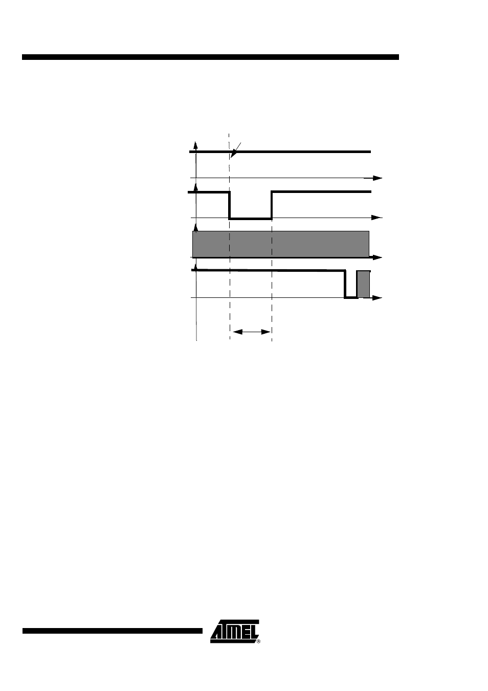
The CRST signal will be equal to 0 during the number of clock cycles programmed in
TIMER_MSB and TIMER_LSB. Then, the CRST signal will be at 1.
Figure 16. Warm reset with ARTn bit = 1
Deactivation Sequence Overview
The deactivation sequence should follows the order defined in ISO7816-3 specification. The
AT83C26 has two deactivation modes:
•
Standard deactivation mode: This mode is used to stop exchange with smart card when the
AT83C26 power supply is present. The DCCLK signal is used for deactivation sequence
timings.
•
Emergency deactivation mode: This mode is used when the AT83C26 power supply is took
off.
Deactivation sequence on SCn interface (n=1, 2, 3, 4, 5)
The card automatic deactivation is triggered when one the following condition occurs:
•
ICARDERR1 bit is set by hardware (SC1)
•
VCARDERRn bit is set by hardware (or by software)
•
INSERT1 is set and CARDIN1 is cleared (SC1)
•
INSERT2 is set and CARDIN2 is cleared (SC2)
•
SHUTDOWNA bit is set by software (SC1)
•
SHUTDOWNB bit is set by software (SC2, SC3, SC4, SC5)
CVCCn
CRSTn
CCLKn
t
CIOn
ART = 1
t = TIMER value