At83c26, Transparent mode – Rainbow Electronics AT83C26 User Manual
Page 29
29
7511B–SCR–10/05
AT83C26
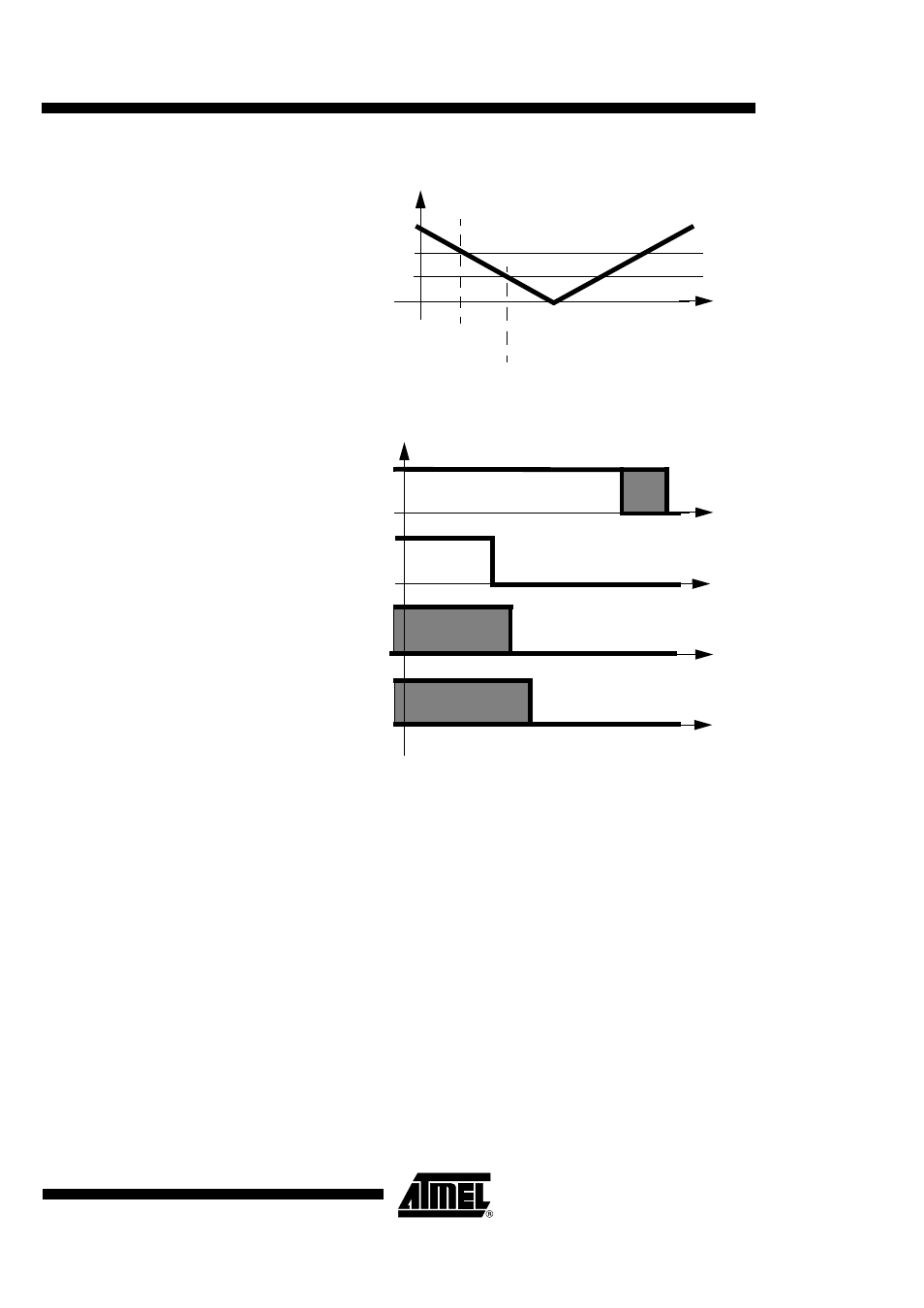
Figure 18. Power Fail Detection
Figure 19. Emergency deactivation sequence
During an emergency deactivation, the signals fall according to the order described in Fig18.
Transparent mode
Full transparent mode on SCn interfaces (n=1, 2)
If the micro controller outputs ISO 7816 signals, a transparent mode allows to connect, CCLK,
CIO, CRST, CC4 and CC8 signals on outputs after an electrical level control. The AT83C26
level shifters adapt the card signals to the smart card voltage selection.
The CCLK micro controller signal can be connected to the A2/CK pins (see CKSn[2:0]).
CKSn[2:0] bits allow to select standard or transparent configuration for the CCLKn pin. A2/CK
inputs always give the TWI address at reset.
If A2/CK input is tied to the host micro controller and its reset value is unknown, a general call on
the TWI bus allows to reset all the AT83C26 devices and set its address after A2/CK input is
fixed.
VCC
VPFDP
VPFDM
start standard deactivation
start emergency deactivation
CVCC
CRST
CCLK
CIO,
CC4,
CC8