At83c26 – Rainbow Electronics AT83C26 User Manual
Page 57
57
7511B–SCR–10/05
AT83C26
Reset value = 0x X000 0000
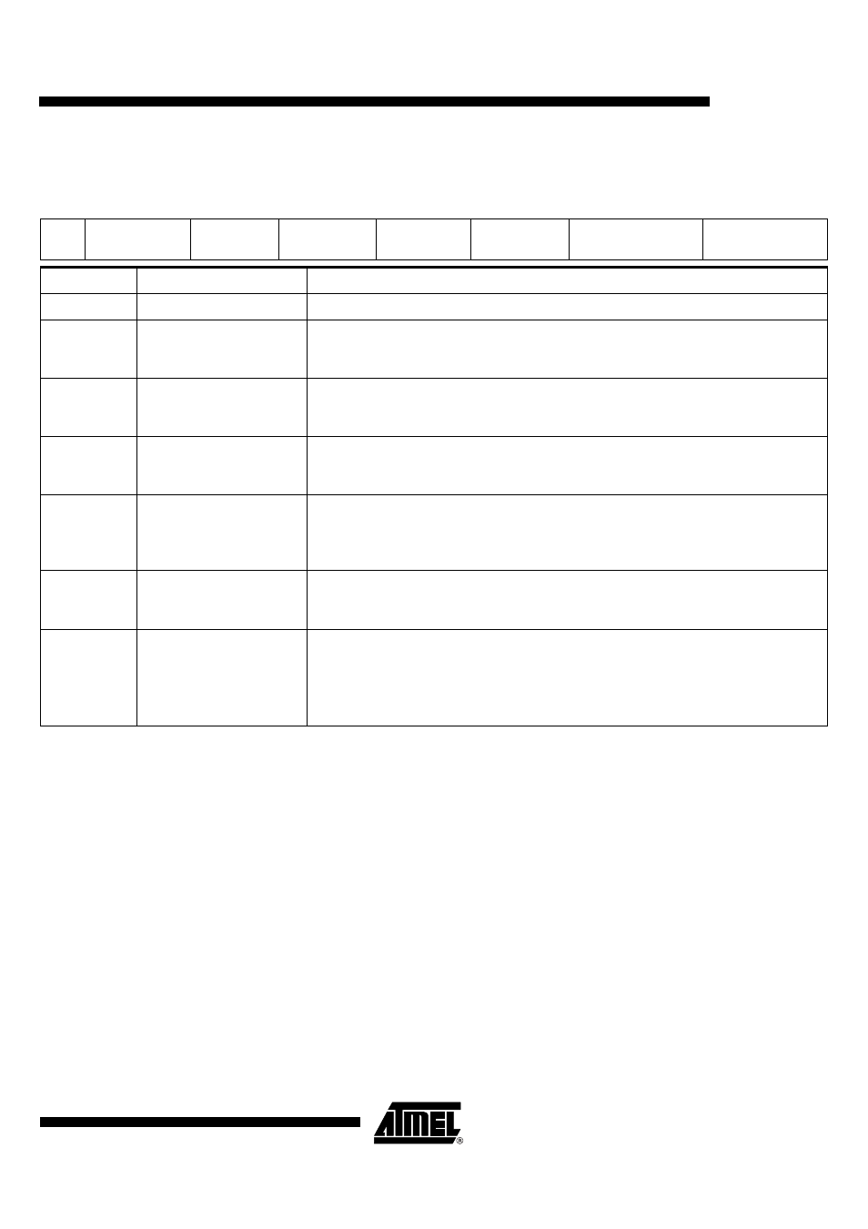
Table 39. INTERFACEB ()
7
6
5
4
3
2
1
0
X
CARDC82
CARDIO5
CARDIO4
CARDIO3/CAR
DC42
CARDIO2
DEMBOOSTB1
DEMBOOSTB0
Bit Number
Bit Mnemonic
Description
7
X
6
CARDC82
Set this bit to drive the CRST3/CC82 pin High with the on-chip pull-up (according to IODIS2 bit
value). The pin can then be an input (read in STATUSB register).
Clear this bit to drive a low level on the CC82 pin (according to IODIS2 bit value).
5
CARDIO5
Set this bit to drive the CIO5 pin High with the on-chip pull-up when isolated from the host (See
“ITDIS ()” on page 59.). The pin can then be an input (read in STATUSB register).
Clear this bit to drive a low level on the CIO5 pin when isolated from the host.
4
CARDIO4
Set this bit to drive the CIO4 pin High with the on-chip pull-up when isolated from the host (See
“ITDIS ()” on page 59.). The pin can then be an input (read in STATUSB register).
Clear this bit to drive a low level on the CIO4/C45 pin when isolated from the host.
3
CARDIO3/
CARDC42
Set this bit to drive the CIO3/CC42 pin High with the on-chip pull-up when isolated from the host
(See “ITDIS ()” on page 59.). The pin can then be an input (read in STATUSB register).
Clear this bit to drive a low level on the CIO3/CC42 pin when isolated from the host.
This bit is CIO3 when AUX=0 or when AUX=1 and IFN=2, otherwise it is CC42.
2
CARDIO2
Set this bit to drive the CIO2 pin High with the on-chip pull-up when isolated from the host (See
“ITDIS ()” on page 59.). The pin can then be an input (read in STATUSB register).
Clear this bit to drive a low level on the CIO2 pin when isolated from the host.
1-0
DEMBOOSTB[1-0]
Configuration for DC/DCB startup current.
00: Normal: 80 mA average
01: Normal + 18%
10: Normal + 18% (and boost on oscillator)
11: Normal + 40%