At83c26 – Rainbow Electronics AT83C26 User Manual
Page 28
28
7511B–SCR–10/05
AT83C26
•
Reset pin going low (SC1, SC2, SC3, SC4, SC5)
•
Power Fail (VPFDP)
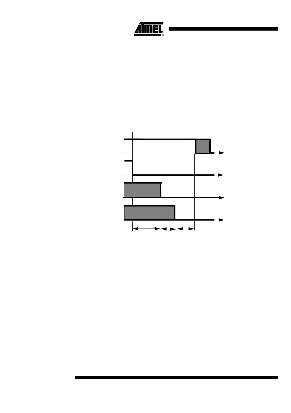
It is a self-timed sequence which cannot be interrupted when started (see Figure 17). Each step
is separated by a delay based on Td equal to 8 periods of DCCLK, typically 2 to 2.4 µs:
1.
T0: CARDRSTn is cleared, SHUTDOWNA (for SC1) bit is set.
2.
T0 + 5 x Td:CARDCKn is cleared, CKSTOPn, CARDIOn and IODIS are set.
3.
T0 + 6 x Td: CARDIOn is cleared.
4.
T0 + 7 x Td: VCARDn[1:0] = 00.
Figure 17. Deactivation Sequence
Notes:
1. Setting ICARDERR1 by software does not trigger a deactivation on SC1. VCARDERRn can
be used to deactivate the card by software.
2. If CCLKn=A2 or A2/2, deactivation follows fig13 with 2 timing modifications: t1=5.5*Td and
t2=0.5*Td.
3. Td is based on DCCLK clock.
Emergency deactivation sequence on SCn interface (n=1, 2, 3, 4, 5)
The card emergency automatic deactivation is triggered when one the following condition
occurs:
•
Software TWI Reset (SC1, SC2, SC3, SC4, SC5)
•
Power fail on VCC (SC1, SC2, SC3, SC4, SC5)
If the power supply is disconnected, a standard deactivation is started when VCC = VPFDP.
When VCC is equal to VPFDM, the emergency deactivation occurs and eventually ends the
standard deactivation.
CVCC
CRST
CCLK
CIO,
5 x Td
Td
Td
CC4,
CC8
t1
t2