At83c26, Cio, cc4, cc8 controller – Rainbow Electronics AT83C26 User Manual
Page 15
15
7511B–SCR–10/05
AT83C26
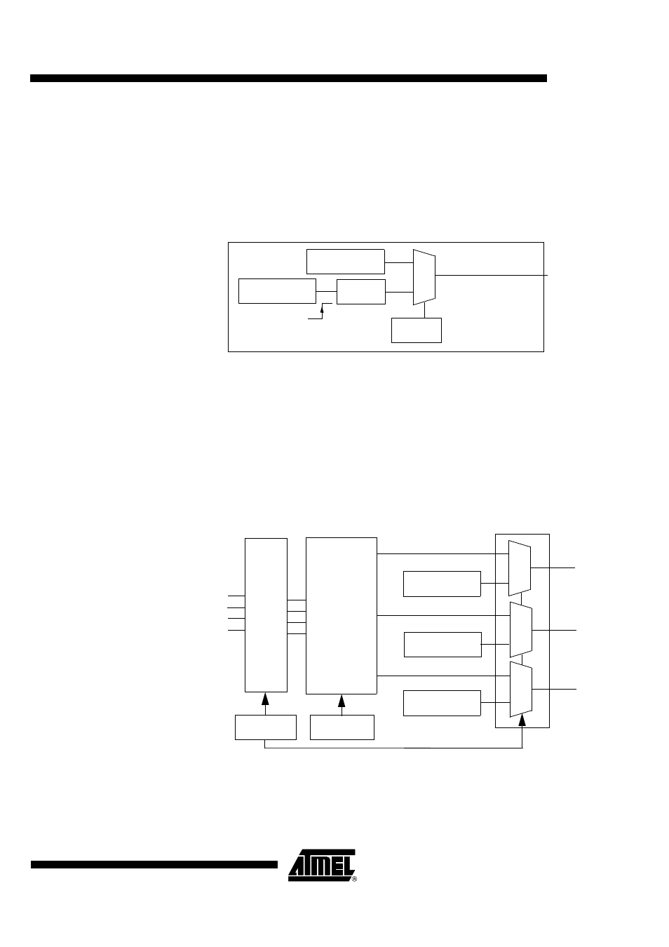
CRSTn for SCn interface (n= 3, 4, 5)
The CRSTn output pin is driven by the CARDRSTn bit value (see SCn_CFG2 register).
Two modes are available:
•
If the ARTn bit is reset, CRSTn pin is driven by CARDRSTn bit.
•
If the ARTn bit is set, CRSTn pin is controlled and follows the “Automatic Reset Transition”
(see Activation sequence page 25).
Figure 6. CRSTn Block Diagram
If SC2_FULL=1, the SC3 interface is not available.
CIO, CC4, CC8 controller
CIO1, CC41, CC81 controller for SC1 interface
The CIO1, CC41, CC81 output pins are driven respectively by CARDIO1, CARDC41, CARDC81
bits values or by I/O1, I/O2, AUX1or AUX2 signals. This selection depends of the IODIS1 bit
value (SC1_INTERFACE register) and of IOSEL[3:0] bits value (IO_SELECT register).
Figure 7. CIO1, CC41, CC81 Block Diagram
If IODIS1 is set, the CARDIO1 bit value is output on CIO1.The input selected by IOSEL for CIO1
is in High impedance state. CC41 and CC81 have the same behavior.
If IODIS1 is reset, data are bidirectional between the I/O1, I/O2, AUX1, AUX2 pins (see
IO_SELECT register) and CIO1, CC41, CC81 pins.
CRSTn
0
1
ARTn bit
CARDRSTn bit
CARDRSTn bit
tb delay
CIO1
0
1
0
1
CARDIO1 bit
CC41
CC81
0
1
CARDC81 bit
IODIS1 bit
CARDC41 bit
IO1
IO2
AUX2
AUX1
IOSEL[3:0]
HiZ
control
Multiplex