At83c26 – Rainbow Electronics AT83C26 User Manual
Page 16
16
7511B–SCR–10/05
AT83C26
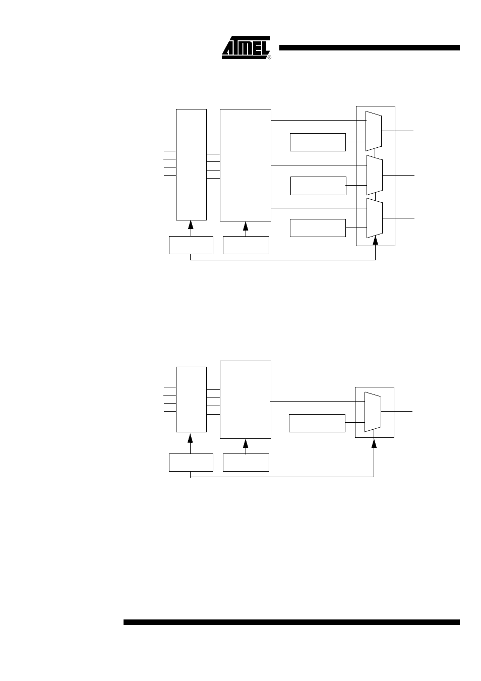
CIO2, CC42, CC82 controller for SC2 interface
Figure 8. CIO2, CC42, CC82 Block Diagram
The SC2_FULL bit must be set to use CC42 and CC82.
CIOn controller for SCn interface (n=3, 4, 5)
The CIOn output pin is driven by CARDIOn bit values or by I/O1, I/O2, AUX1 or AUX2 signals.
This selection depends of the IODISn bit value. If IODISn is reset, data are bidirectional between
the I/O1, I/O2, AUX1, AUX2 pins (see IO_SELECT register) and CIOn pins.
Figure 9. CIOn Block Diagram
CIOn (n=1 to 5), CC41, CC81, CC42, CC82 transparent mode description
Two modes are available on CIOn, CC4n, CC8n signals:
•
Bit control (a bit controls the output pin)
•
Transparent mode (IO signal and CIO are linked after level shifter)
According to IO_SELECT register value and IODISn bits values, one of 4 input pins (IO1, IO2,
AUX1 or AUX2) is linked to the selected output.
The idle state is the high level. Each signal is bidirectional.
CIO2
0
1
0
1
CARDIO2 bit
CC42
CC82
0
1
CARDC82 bit
CARDC42 bit
IO1
IO2
AUX2
AUX1
HiZ
control
Multiplex
IODIS2 bit
IOSEL[3:0]
CIOn
0
1
CARDIOn bit
IODISn bit
IO1
IO2
AUX2
AUX1
IOSEL[3:0]
HiZ
control
Multiplex