At83c26, Read command – Rainbow Electronics AT83C26 User Manual
Page 35
35
7511B–SCR–10/05
AT83C26
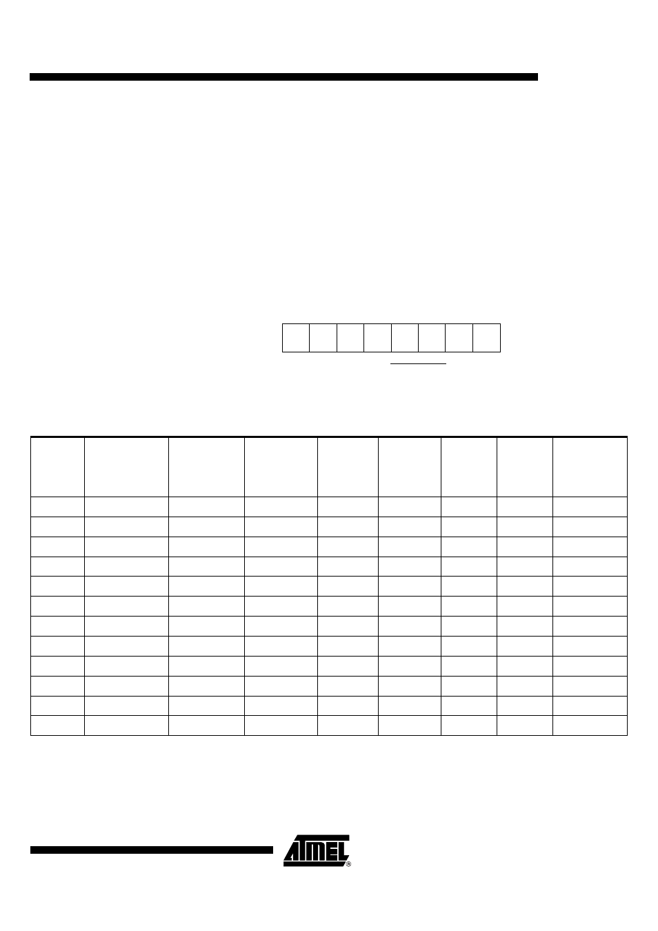
Read Command
After a write command, even with a length of 0 byte, the next read operation is performed on the
corresponding byte. The write command sets the “read pointer”.
After the reset, the “read pointer” is on SC1 registers
FFh is completing the transfer if the micro controller attempts to read beyond the last byte.
Flags are only reseted after the corresponding byte read has been acknowledged by the master.
Figure 23. Read command byte
Table 7. Read Commands Description
b7
b6
b5
b4
b3
b2
b1
0
0
1
0
X
X
1
levels on reset
b0
1
A2
A1
1. After reset or
write command
number 2, 3, 4
2. After
write
command
number 6
3. After
write command
number 7
4. After
write
command
number 8
5. After
write
command
number 9
6. After
write
command
number 10
7. After
write
command
number 11
8. After
write
command
number 12
[0]
SC1_STATUS
STATUSB
SC2_CFG0
SC3_CFG0
SC4_CFG0
SC5_CFG0
DCDCB
SLEW_CTRL_1
[1]
SC1_CFG0
IO_SELECT
SC2_CFG1
SC3_CFG2
SC4_CFG2
SC5_CFG2
LDO
SLEW_CTRL_2
[2]
SC1_CFG1
INTERFACE_B
SC2_CFG2
0xFF
0xFF
0xFF
0xFF
SLEW_CTRL_3
[3]
SC1_CFG2
ITDIS
0xFF
0xFF
0xFF
0xFF
0xFF
0xFF
[4]
SC1_CFG3
0xFF
0xFF
0xFF
0xFF
0xFF
0xFF
0xFF
[5]
SC1_CFG4
0xFF
0xFF
0xFF
0xFF
0xFF
0xFF
0xFF
[6]
SC1_INTERFACE
0xFF
0xFF
0xFF
0xFF
0xFF
0xFF
0xFF
[7]
TIMER_MSB
0xFF
0xFF
0xFF
0xFF
0xFF
0xFF
0xFF
[8]
TIMER_LSB
0xFF
0xFF
0xFF
0xFF
0xFF
0xFF
0xFF
[9]
CAPTURE_MSB
0xFF
0xFF
0xFF
0xFF
0xFF
0xFF
0xFF
[10]
CAPTURE_LSB
0xFF
0xFF
0xFF
0xFF
0xFF
0xFF
0xFF
[11]
0xFF
0xFF
0xFF
0xFF
0xFF
0xFF
0xFF
0xFF