At83c26, Registers – Rainbow Electronics AT83C26 User Manual
Page 38
38
7511B–SCR–10/05
AT83C26
Registers
Reset value = 0x 1000 0000
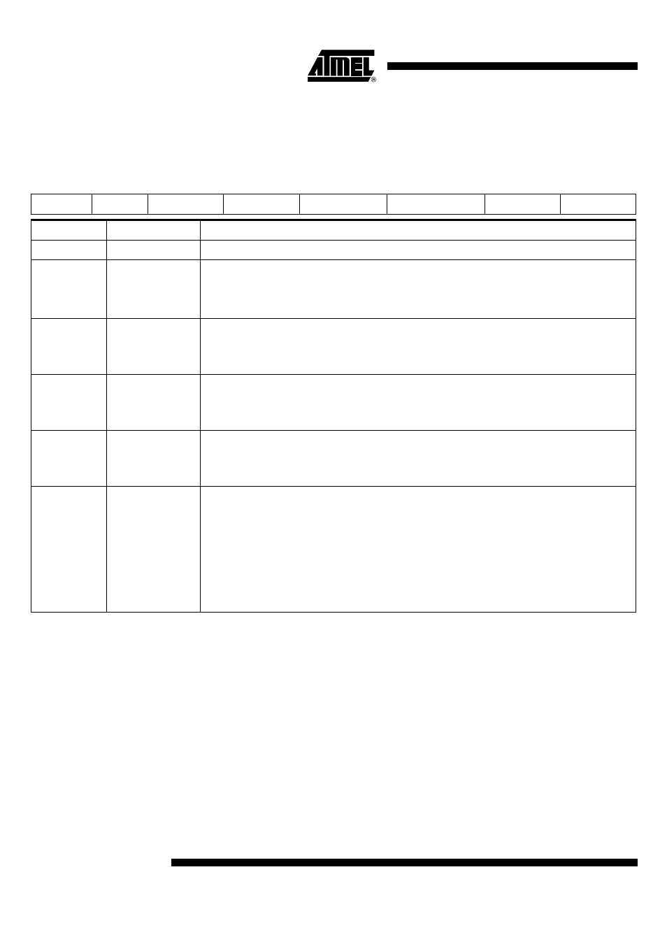
Table 17. SC1_ CFG0(Config Byte 0 for SC1)
7
6
5
4
3
2
1
0
1
0
ATRERR1
INSERT1
ICARDERR1
VCARDERR1
VCARD11
VCARD10
Bit Number
Bit Mnemonic
Description
7-6
1-0
These bits cannot be programmed and are read as 1-0.
5
ATRERR1
Answer to Reset Interrupt for SC1
This bit is set when the card clock counter overflows (no falling edge on CIO1 is received before the overflow
of the card clock counter).
This bit is cleared by hardware when this register is read. It can be set by software for test purpose.
4
INSERT1
Card Insertion Interrupt
This bit is set when a card is inserted or extracted: a change in CARDIN value filtered according to CDS[2-0].
It can be set by software for test purpose.
This bit is cleared by hardware when this register is read. It cannot be cleared by software.
3
ICARDERR1
Card Over Current Interrupt
This bit is set when an over current is detected on CVCC. It can be set by software for test purpose (no card
deactivation is performed).
This bit is cleared by hardware when this register is read. It cannot be cleared by software.
2
VCARDERR1
Card Out of Range Voltage Interrupt
This bit is set when the output voltage goes out of the voltage range specified by VCARD field. It can be set
by software for test purpose and deactivate the card.
This bit is cleared by hardware when this register is read. It cannot be cleared by software.
1-0
VCARD1[1:0]
Card Voltage Selection
VCARD1[1:0] = 00: 0V
VCARD1[1:0] = 01: 1.8V
VCARD1[1:0] = 10: 3V
VCARD1[1:0] = 11: 5V
VCARD1[1:0] writing to 1.8V, 3V, 5V starts the DC/DC if a card is detected.
VCARD1[1:0] writing to 0 stops the DC/DC.
No card deactivation is performed when the voltage is changed between 1.8V, 3V or 5V. The micro controller
should deactivate the card before changing the voltage.