At83c26, Address byte – Rainbow Electronics AT83C26 User Manual
Page 11
11
7511B–SCR–10/05
AT83C26
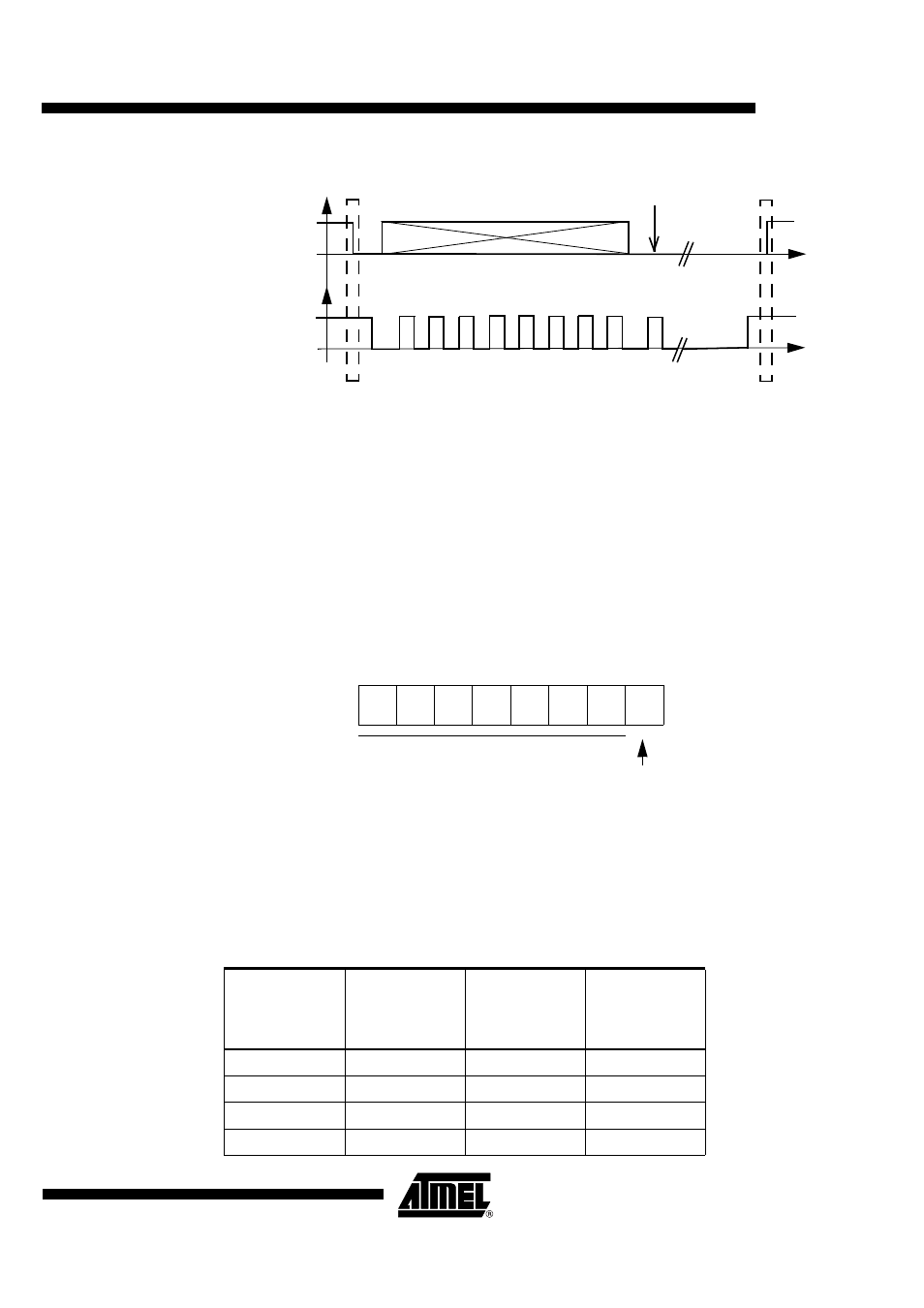
Figure 1. Data transfer on TWI bus
Address Byte
The first byte to send to the device is the address byte. The device controls if the hardware
address (A2/CK, A1/RST pins on reset) corresponds to the address given in the address byte
(A2, A1 bits).
If the level is not stable on A2/CK pin at reset, the user has to manage the possible address
taken by the device.
Figure 2. Address Byte
Up to 4 devices can be connected on the same TWI bus. Each device is configured with a differ-
ent combination on A2/CK, A1/RST pins. The address byte of each device for read/write
operations are listed below.
SDA
SCL
start condition
stop condition
1
2
3
4
5
6
7
8
9
acknowledgement
from slave
Address byte
command
and/or data
Table 2. Address Byte Values
A2
(A2/CK pin)
A1
(A1/RST pin)
Address Byte
for
Read
Command
Address Byte
for
Write
Command
0
0
0x43
0x42
0
1
0x47
0x46
1
0
0x4B
0x4A
1
1
0x4F
0x4E
b7
b6
b5
b4
b3
b2
b1
b0
0
0
1
0
A2
A1
1
R/W
Slave Address on 7 Bits
1 for READ Command
0 for WRITE Command