At83c26 – Rainbow Electronics AT83C26 User Manual
Page 21
21
7511B–SCR–10/05
AT83C26
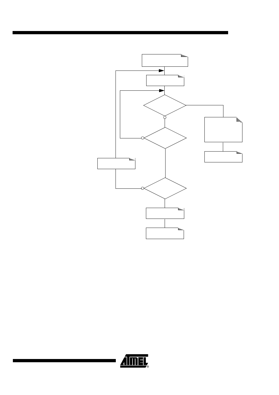
Figure 9. DC/DC A Converter Initialization Procedure
DC/DC B converter
The DC/DC B converter is controlled by DCDCB register.
The DC/DC B converter can be switched on even if CPRES2 pin remains inactive.
A write operation in VDCB[1:0] (0x01, 0x02, 0x03) starts the DC/DC. When the output voltage
remains within the voltage range specified by VDCB_OK[1:0], the VDCB_OK bit is set.
The DC/DC B Converter can work in two different modes which are selected by STEPREGB:
•
Pump Mode (STEPREGB = 0): an external inductance of 10 µH must be connected
between pins LIB and VCC. VCC can be higher or lower than selected voltage.
•
Regulator mode (STEPREGB = 1): no external inductance is required but VCC must be
always higher than selected voltage+0.3V.
The current drawn from power supply by the DC/DC B converter is controlled during the startup
phase in order to avoid high transient current mainly in Pump Mode which could cause the
power supply voltage to drop dramatically. This control is done by means of bits DEM-
BOOSTB[1:0], which increases progressively the startup current level.
DEMBOOSTA[1:0]=[0:0]
VCARD_OK1=1
Set Time-out to 3 ms
Time-out
Expired
DEMBOOSTA[1:0]
is at Maximum?
DC/DC A Converter
Initialization Failure
END
END
Decrement
DEMBOOSTA[1:0]
to adjust the
current overflow
Increment
DEMBOOSTA[1:0]