At83c26 – Rainbow Electronics AT83C26 User Manual
Page 40
40
7511B–SCR–10/05
AT83C26
Reset value = 0x 0001 X000
Notes:
1. When CKS1 value is changed a special logic insures no glitch occurs on the CCLK1 pin and
actual configuration changes can be delayed by half a period to two periods of CCLK1.
2. CCLK1 must be stopped with CKSTOP1 bit before switching from CKS1 = (0, 1, 2, 3, 6, 7) to
CKS1 = (4, 5) or vice versa.
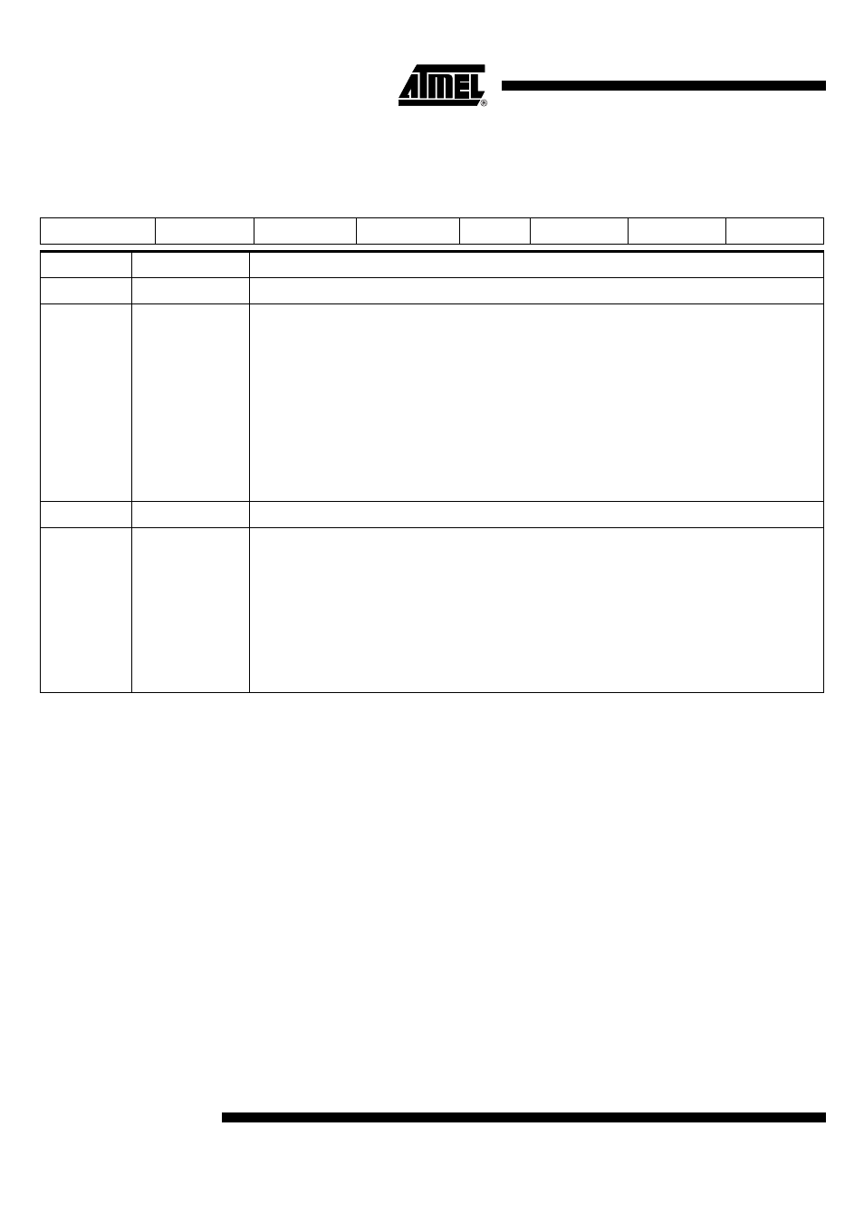
Table 19. SC1_CFG2 (Config Byte 2 for SC1)
7
6
5
4
3
2
1
0
0
DCK2
DCK1
DCK0
X
CKS12
CKS11
CKS10
Bit Number
Bit Mnemonic
Description
7
0
This bit must be always at 0.
6-4
DCK[2:0]
DCK is the first level of prescaler factor. CLK signal is divided by the prescaler value and outputs DCCLK
signal. DCCLK is an input for CCLK prescaler.
DCK[2:0] = 0: prescaler factor equals 1
DCK[2:0] = 1: prescaler factor equals 2
DCK[2:0] = 2: prescaler factor equals 4
DCK[2:0] = 3: prescaler factor equals 6
DCK[2:0] = 4: prescaler factor equals 8
DCK[2:0] = 5: prescaler factor equals 10
DCK[2:0] = 6: prescaler factor equals 12
DCK[2:0] = 7: Reserved
DCCLK is used for pad management and dectivation sequence.
3
X
2-0
CKS1[2:0]
Card Clock prescaler factor for CCLK1.
CKS1 [2:0] = 0: CCLK1 = CLK (the maximum frequency on CLK is 24 MHz)
CKS1 [2:0] = 1: CCLK1 = DCCLK
CKS1[2:0] = 2: CCLK1 = DCCLK / 2
CKS1[2:0] = 3: CCLK1 = DCCLK / 4
CKS 1[2:0] = 4: CCLK1 = A2
CKS1 [2:0] = 5: CCLK1 = A2 / 2
CKS1[2:0] = 6: CCLK1 = CLK / 2
CKS1 [2:0] = 7: CCLK1 = CLK / 4