At83c26 – Rainbow Electronics AT83C26 User Manual
Page 39
39
7511B–SCR–10/05
AT83C26
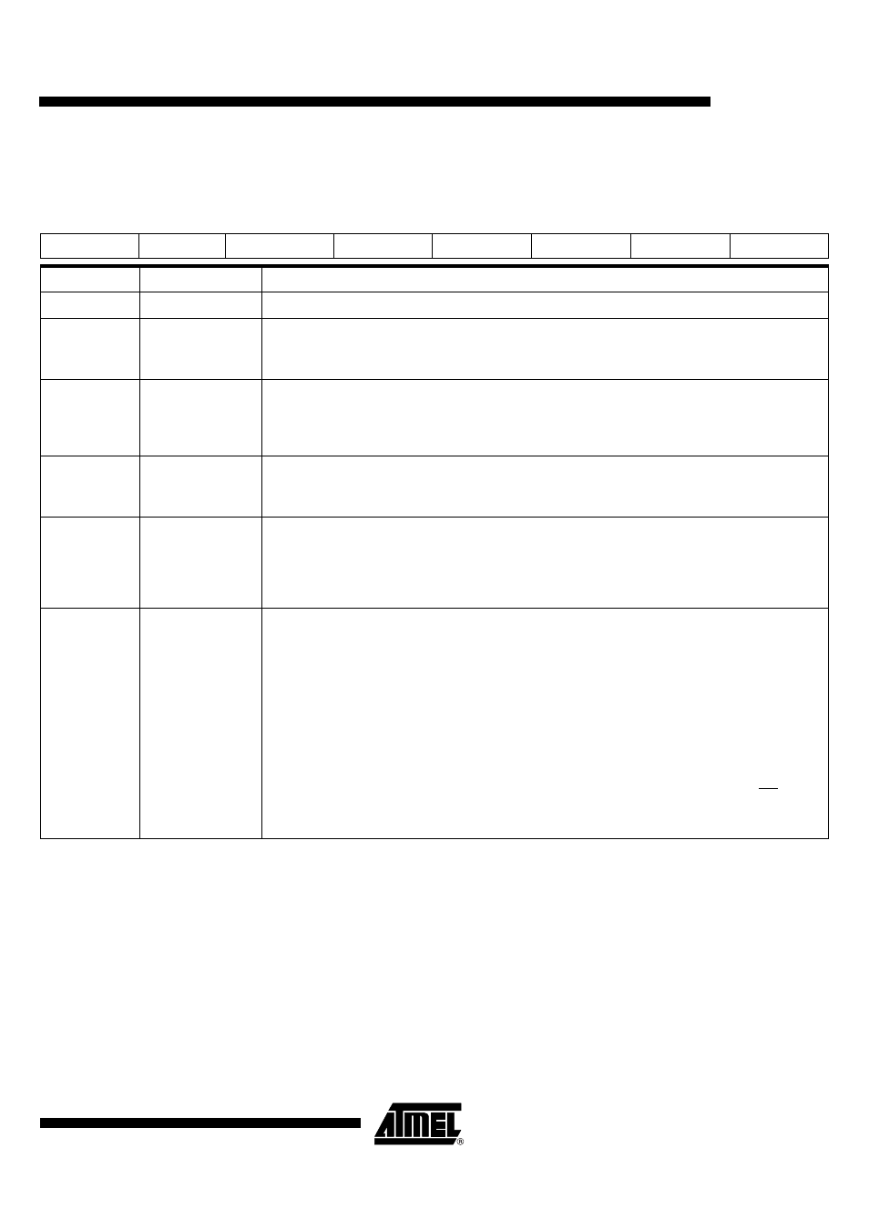
SC1_CFG
Reset value = 0x X000 1010
Table 18. SC1_CFG1 (Config Byte 1 for SC1
7
6
5
4
3
2
1
0
X
ART1
SHUTDOWNA
CARDDET1
PULLUP1
CDS12
CDS11
CDS10
Bit Number
Bit Mnemonic
Description
7
X
6
ART1
Automatic Reset Transition
Set this bit to have the CRST1 pin changed according to activation sequence.
Clear this bit to have the CRST1 pin immediately following the value programmed in CARDRST1.
5
SHUTDOWNA
Shutdown DC/DCA
Set this bit to reduce the power consumption. An automatic de-activation sequence will be done.
VCARD[1:0] bits are reset.
Clear this bit to enable VCARD1[1:0] selection.
4
CARDDET1
Card Presence Detection Polarity
Set this bit to indicate the card presence detector is closed when no card is inserted (CPRES is low).
Clear this bit to indicate the card presence detector is open when no card is inserted (CPRES is high).
3
PULLUP1
Pull-up Enable
Set this bit to enable the internal pull-up on the CPRES pin. This allows to minimize the number of external
components.
Clear this bit to disable the internal pull-up and minimize the power consumption when the card detection
contact is on. Then an external pull-up must be connected to V
CC
(typically a 1 M
Ω
resistor).
2-0
CDS1[2:0]
Card Detection filtering
CPRES1 is sampled by the master clock provided on CLK input. A change on CPRES1 is detected after:
CDS1[2-0] = 0: no sample
(1)
CDS1[2-0] = 1: 4 identical samples
CDS1[2-0] = 2: 8 identical samples (reset value)
CDS1[2-0] = 3: 16 identical samples
CDS1[2-0] = 4: 32 identical samples
CDS1[2-0] = 5: 64 identical samples
CDS1[2-0] = 6: 128 identical samples
CDS1[2-0] = 7: 256 identical samples
Note:
1.
When CDS[2-0] = 0, a card insertion (even if CLK is stopped) puts a low level on INT pin. This
can be used to wake up the external micro controller and restart CLK when a card is inserted
in the AT83C24.