Absolute maximum ratings, Dc characteristics – Rainbow Electronics AT86RF401 User Manual
Page 8
8
AT86RF401
1424D–RKE–09/02
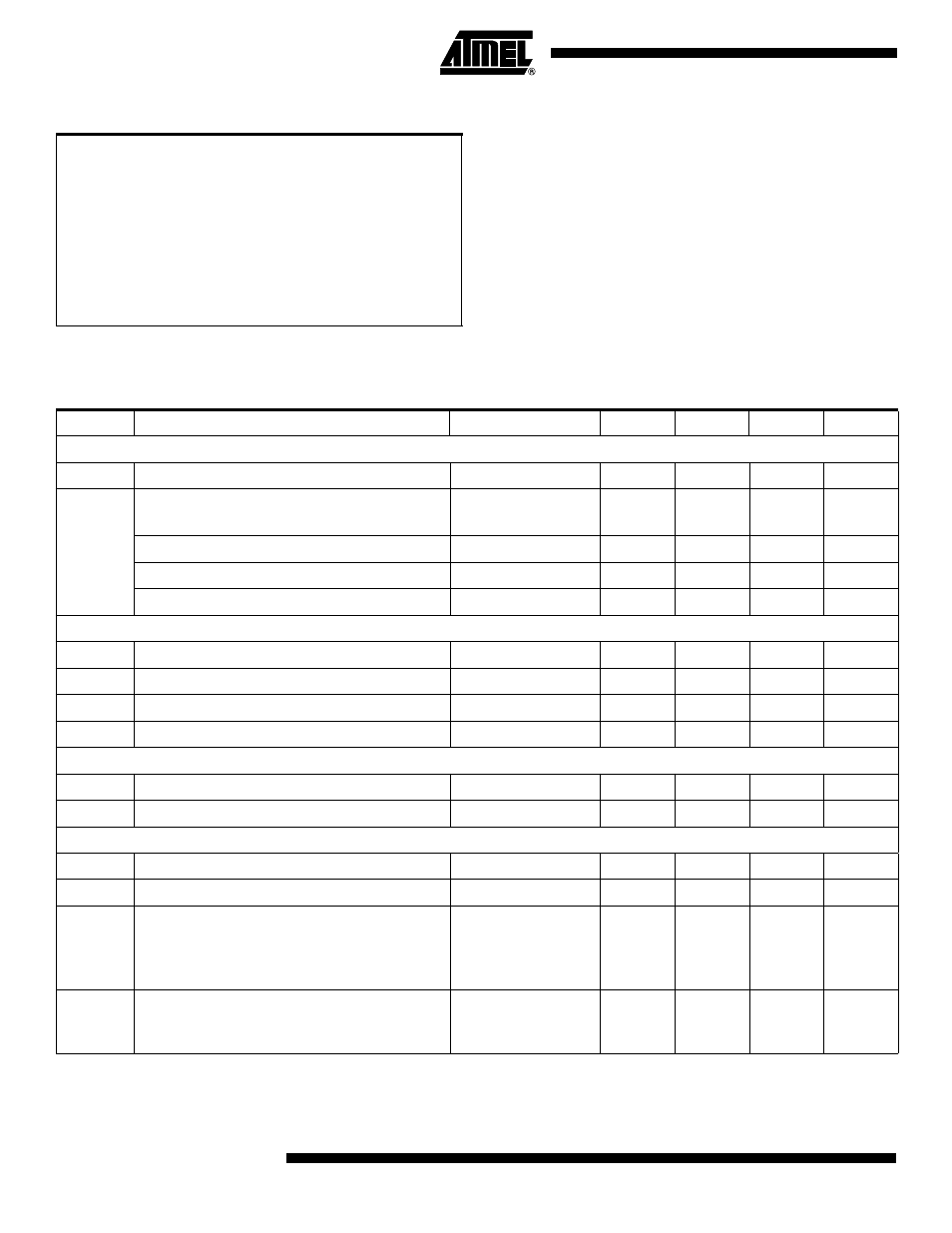
Absolute Maximum Ratings*
Antenna Voltage (Pins 1, 20)
......................................−1V to 10V
*NOTICE:
Stresses beyond those listed under “Absolute
Maximum Ratings” may cause permanent dam-
age to the device. This is a stress rating only;
functional operation of the device at these or
other conditions beyond those indicated in the
operational sections of this specification is not
implied. Exposure to absolute maximum rating
conditions for extended periods may affect device
reliability.
Operating Temperature
........................................−40°C to +85°C
Storage Temperature (without bias)
................−55°C to +125°C
Voltage on V
DD
with respect to ground ............................. 6.0V
Voltage on Pins 2–19 (TSSOP 20)
................ −0.1 to V
DD
+0.3V
DC Characteristics
V
DD
= 3.3V; f
XTAL
= 13.125 MHz; f
AVR
= f
XTAL
÷ 16; T
A
= 25°C unless otherwise specified.
Symbol
Parameter
Conditions
Min
Typ
Max
Unit
Supply
V
DD
Supply Voltage
2.0
3.3
5.0
V
I
DD
Standby Current (off)
V
DD
= 3.3V
T
A
=
25°C
–
0.1
0.5
µA
AVR Active
–
3.4
–
mA
Frequency Synthesizer + AVR Active
–
14.3
–
mA
Transmit (FS, AVR and Power Amp active)
CW modulation
–
23.2
–
mA
Digital Inputs (SDI, SCK, RESETB, IOx)
V
IH
High-level Input Voltage
0.8* V
DD
–
V
DD
V
V
IL
Low-level Input Voltage
0
–
0.2* V
DD
V
I
IH
High-level Input Current
V
IH
= V
DD
,
V
DD
= 5.0V
–
–
1
µA
I
IL
Low-level Input Current
V
IL
= 0V
,
V
DD
= 5.0V
−140
–
–
µA
Digital Outputs (SDO, IOx)
V
OH
High-level Output Voltage
I
OH
=
−500 µA
V
DD
−0.4
–
–
V
V
OL
Low-level Output Voltage
I
OL
= 2 mA
–
–
0.4
V
Microcontroller/System
t
TX
Time from Button Wake-up to RF Outputs Active
–
0.5
1.0
ms
f
AVR
AVR Clock Frequency
–
–
1.25
MHz
EE
LIFE
EEPROM Retention
Initial programming
conditions:
V
DD
= 3.3V ± 10%
Temp = 25
°C ± 10%
–
–
10
years
EE
CYCLES
EEPROM Write/Erase Endurance
2.0V
≤ V
DD
≤ 5.0V
−40°C ≤ Temp ≤
85
°C
–
–
100,000
cycles