I/o memory – Rainbow Electronics AT86RF401 User Manual
Page 28
28
AT86RF401
1424D–RKE–09/02
I/O Memory
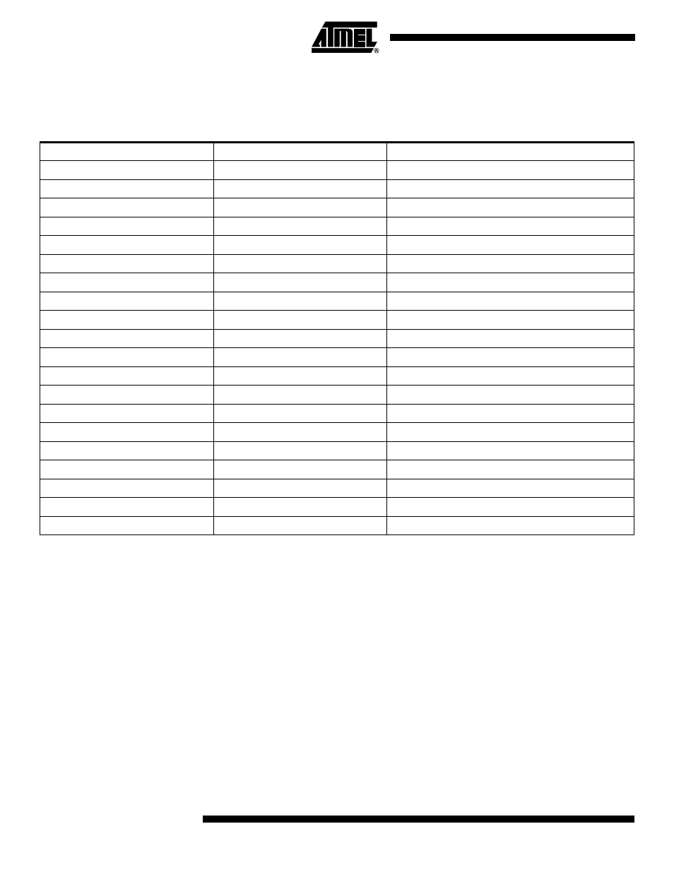
The I/O space definition of the AT86RF401 is shown in Table 7 below.
Note:
Reserved and unused locations are not shown in the table.
Table 7. AT86RF401 I/O Space Definitions
Address Hex
Name
Function
$3F
SREG
Status Register
$3E
SPH
Stack Pointer High Register (program to 0 x 00)
$3D
SPL
Stack Pointer Low Register
$35
BL_CONFIG
Battery Low Configuration Register
$34
B_DET
Button Detect Register
$33
AVR_CONFIG
AVR Configuration Register
$32
IO_DATIN
I/O DATA IN Register
$31
IO_DATOUT
I/O DATA OUT Register
$30
IO_ENAB
I/O Enable Register
$22
WDTCR
Watchdog Timer Control Register
$21
BTCR
Bit Timer Control Register
$20
BTCNT
Bit Timer Count Register
$1E
DEEAR
Data EEPROM Address Register
$1D
DEEDR
Data EEPROM Data Register
$1C
DEECR
Data EEPROM Control Register
$17
LOCKDET2
Lock Detector Configuration Register 2
$16
VCOTUNE
VCO Tuning Register
$14
PWR_ATTEN
Power Attenuation Control Register
$12
TX_CNTL
Transmitter Control Register
$10
LOCKDET1
Lock Detector Configuration Register 1