I/o enable register – io_enab – Rainbow Electronics AT86RF401 User Manual
Page 39
39
AT86RF401
1424D–RKE–09/02
bit is set (“1”). To disable an enabled Watchdog Timer, the following procedure must be
followed: In the same operation, write a logical “1” to WDTOE and WDE. A logical “1”
must be written to WDE even though it is set to “1” before the disable operation starts.
Within the next four clock cycles, write a logical “0” to WDE. This disables the watchdog.
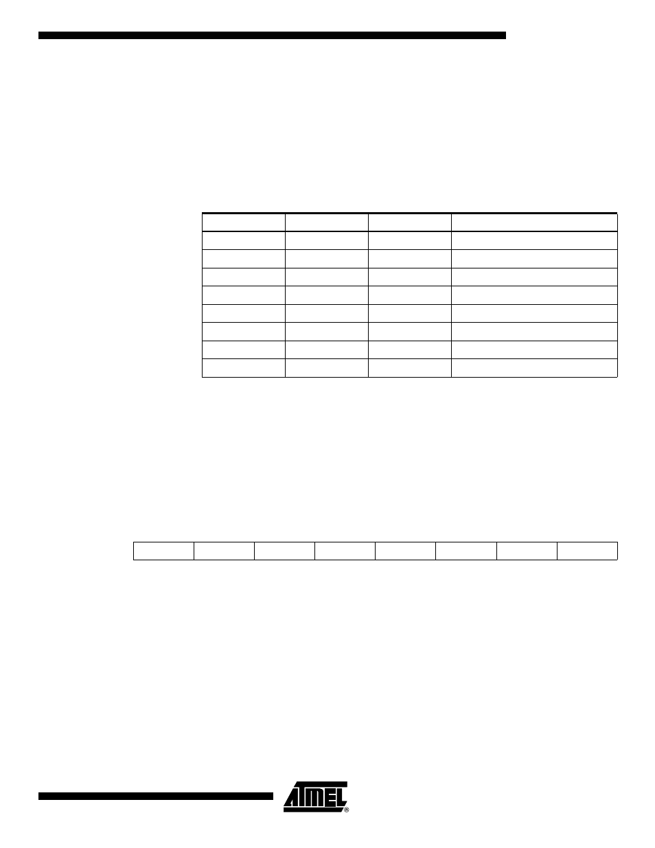
• Bits[2:0]: WDP2, WDP1, WDP0, Watchdog Timer Prescaler 2, 1 and 0
The WDP2, WDP1 and WDP0 bits determine the Watchdog Timer prescaling when the
Watchdog Timer is enabled. The different prescaling values and their corresponding
time-out periods are shown in Table 9.
Note:
Example:
If the crystal period is 50 ns and the system clock divider is set to 32 (Bits[7:5] in the
PWR_CTL register are set to 010) and the WDT prescaler is set to 32K, then:
Watchdog Timeout = 50 ns
Ч 32 Ч 32768 = 52 ms
I/O Enable Register – IO_ENAB
• Bit[7]
Reserved.
• Bit[6]
If set to “1”, additional hysteresis is added to the battery low and brown-out logic. See
BL_CONFIG register description and Table 3 (page 10) for more details.
Table 9. Watchdog Timer Prescale Select
WDP2
WDP1
WDP0
Number of System Clock Cycles
0
0
0
2,048 cycles
0
0
1
4,096 cycles
0
1
0
8,192 cycles
0
1
1
16,384 cycles
1
0
0
32,768 cycles
1
0
1
65,536 cycles
1
1
0
131,072 cycles
1
1
1
262,144 cycles
T
wdt
XTALB
period
ACS
div
WDT
div
Ч
Ч
=
Bit
7
6
5
4
3
2
1
0
$30
–
BOHYST
IOE5
IOE4
IOE3
IOE2
IOE1
IOE0
Read/Write
R/W
R/W
R/W
R/W
R/W
R/W
R/W
R/W
Initial Value
0
0
0
0
0
0
0
0