Bit timer register descriptions, Bit timer count register – btcnt, Bit timer control register – btcr – Rainbow Electronics AT86RF401 User Manual
Page 37
37
AT86RF401
1424D–RKE–09/02
Bit Timer Register Descriptions
Bit Timer Count Register – BTCNT
• Bit [7:0]
Lowest 8 bits of
countval. When combined with bits [7:6] of the BTCR register, countval
determines a counter value that sets the width of a mark or a space that is sent to the
transmitter. The width of the mark or space is:
P
XX
= P
AVR
*
(countval +1)
where
P
XX
is the period of the mark or space, and
P
AVR
is the period of the AVR clock
that is determined by the ACS bits of the AVR configuration register, AVR_CONFIG.
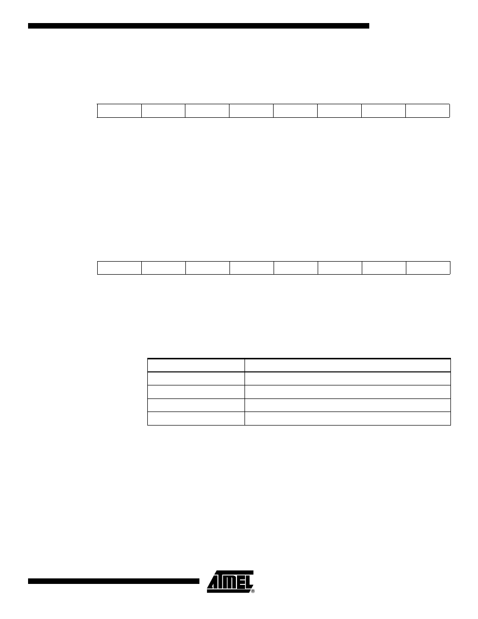
Bit Timer Control Register – BTCR
• Bit[7:6]
Count_val[9:8]. MSB of BTCNT counter value bits.
• Bits[5:4]
Bit Timer Mode.
• Bit[3]: Interrupts Enabled
If this bit is set, the Flag2 and Flag0 will generate their respective interrupts when they
are set. Flag0 interrupt vector is located at 0 x 04. Flag2 interrupt vector is located at
0 x 02. Typically, a JMP instruction resides at these vector locations to pass control to
an interrupt handler. For Flag0 only, slightly faster execution can be achieved if the JMP
instruction is eliminated, and the interrupt service routine is located beginning at 0 x 04.
Bit
7
6
5
4
3
2
1
0
$20
C7
C6
C5
C4
C3
C2
C1
C0
Read/Write
R/W
R/W
R/W
R/W
R/W
R/W
R/W
R/W
Initial Value
0
0
0
0
0
0
0
0
Bit
7
6
5
4
3
2
1
0
$21
C9
C8
M1
M0
IE
F2
DATA
F0
Read/Write
R/W
R/W
R/W
R/W
R/W
R
R/W
R
Initial Value
0
0
0
0
0
0
0
0
Mode[1:0]
Bit Timer Function
00
Bit Timer Disabled
01
Transmit Mode, Transmitter Not Keyed
10
Receive Mode
11
Transmit Mode, Transmitter Keyed