Bandgap reference, Brown-out protection/low battery detection, Brown-out protection – Rainbow Electronics AT86RF401 User Manual
Page 10: Low battery detection
10
AT86RF401
1424D–RKE–09/02
period. A number of registers are available to adjust the performance of the lock detec-
tor. These include lock delay and unlock delay timers as well as a cycle slip counter.
Bandgap Reference
The device uses a 1.2V (nominal) bandgap reference generator to provide consistent
performance over a wide range of input supply voltages. This reference voltage is used
throughout the device.
Brown-out Protection/Low
Battery Detection
The brown-out protection and low battery detection functions consist of a voltage refer-
ence, a sampling block and an autozero comparator. The circuit’s primary operating
mode is brown-out protection.
Brown-out Protection
The brown-out protection circuit detects when the level of V
DD
drops below the minimum
voltage that guarantees proper operation. The brown-out voltage for this device is typi-
cally 1.8 volts.
If a brown-out occurs, the device enters a reset state. It stays in this state until either of
the following occurs:
•
The level of V
DD
increases ~0.1–0.2 volts above the brown-out voltage. This causes
the device to enter a warm reboot state.
•
The level of V
DD
drops to ~0 volts, then increases above the POR level. This places
the device into the “cold start” mode of operation, identical to battery insertion.
Low Battery Detection
The low battery detection feature allows the programmer to select a value for V
DD
at
which a warning is issued to the user. This warning may be utilized to activate an I/O
port, for example.
If low battery detection occurs, Bit 7 of register BL_CONFIG is set. Bit 6 of register
BL_CONFIG is used to indicate that Bit 7 is valid. It is left to the programmer to poll both
bits to ensure the potential warning is valid.
Bits 5–0 of register BL_CONFIG are used to program the low battery detect level. This
warning level is programmable between ~1.5–2.7 volts.
Note:
The warning level can be set below the brown-out voltage level.
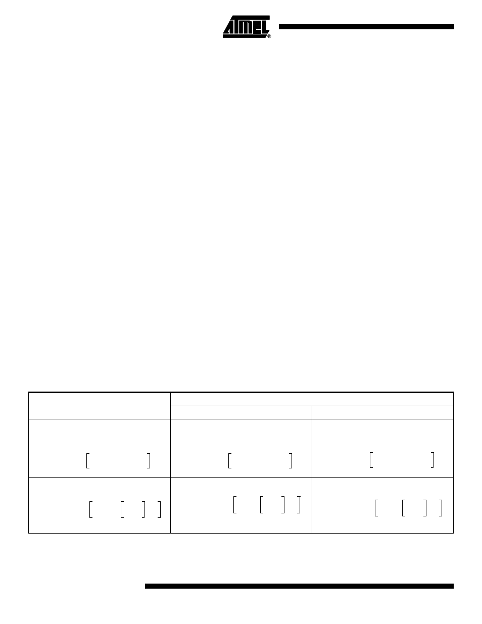
The formula for calculating the low battery detection threshold is located in Table 3.
Table 3. Low Battery Detection Threshold Formulas (V
REF
is approximately 0.7 volts)
V
DD
Falling
V
DD
Rising
bo_hyst = 1 (large hysteresis)
bo_hyst = 0 (small hysteresis)
VDD
3.887
V
REF
Ч
1
0.887
63
---------------
Ч BL[5:0]
+
-----------------------------------------------------------
=
VDD
4.05
V
REF
Ч
1
0.887
63
---------------
Ч BL[5:0]
+
-----------------------------------------------------------
=
VDD
4.22
V
REF
Ч
1
0.887
63
---------------
Ч BL[5:0]
+
-----------------------------------------------------------
=
BL[5:0]
71
3.887
V
REF
V
D D
-------------
1
–
Ч
Ч
=
BL[5:0]
71
4.05
V
REF
V
D D
-------------
1
–
Ч
Ч
=
BL[5:0]
71
4.22
V
REF
V
D D
-------------
1
–
Ч
Ч
=