The stack pointer – sp, The status register – sreg – Rainbow Electronics AT86RF401 User Manual
Page 43
43
AT86RF401
1424D–RKE–09/02
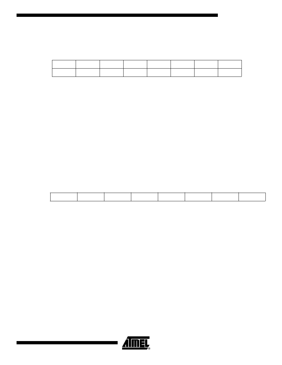
The Stack Pointer – SP
The Stack Pointer is implemented as two 8-bit registers in the I/O space locations $3E
($5E) and $3D ($5D). Caution: As the data memory has 224 locations, only 8 bits are
used and the SPH register must be programmed to 0 x 00.
The Stack Pointer points to the data SRAM stack area where the Subroutine and Inter-
rupt Stacks are located. This stack space in the data SRAM must be defined by the
program before any subroutine calls are executed or interrupts are enabled. The Stack
Pointer must be set to point above $60. The Stack Pointer is decremented by one when
data is pushed onto the stack with the PUSH instruction, and it is decremented by two
when the return address is pushed onto the stack with subroutine call and interrupt. The
Stack Pointer is incremented by one when data is popped from the stack with the POP
instruction, and it is incremented by two when data is popped from the stack with Return
from Subroutine (RET) or Return from Interrupt (RETI).
The Status Register – SREG
The AVR status register – SREG – at I/O space location $3F is defined as:
• Bit[7] – I: Global Interrupt Enable
The global interrupt enable bit must be set (“1”) for the interrupts to be enabled. The
individual interrupt enable control is then performed in the interrupt mask registers
(GIMSK/TIMSK). If the global interrupt enable register is cleared (“0”), none of the inter-
rupts are enabled, independent of the GIMSK/TIMSK values. The I-bit is cleared by
hardware after an interrupt has occurred and is set by the RETI instruction to enable
subsequent interrupts.
• Bit[6] – T: Bit Copy Storage
The bit copy instructions BLD (Bit LoaD) and BST (Bit STore) use the T-bit as source
and destination for the operated bit. A bit from a register in the register file can be copied
into T by the BST instruction, and a bit in T can be copied into a bit in a register in the
register file by the BLD instruction.
• Bit[5] – H: Half Carry Flag
The half carry flag H indicates a half carry in some arithmetic operations. See Table 10,
“SRAM Organization,” on page 21 for detailed information.
Bit
15
14
13
12
11
10
9
8
$3E
–
–
–
–
–
SP10
SP9
SP8
SPH
$3D
SP7
SP6
SP5
SP4
SP3
SP2
SP1
SP0
SPL
7
6
5
4
3
2
1
0
Read/Write
R
R
R
R
R
R/W
R/W
R/W
R/W
R/W
R/W
R/W
R/W
R/W
R/W
R/W
Initial Value
0
0
0
0
0
0
0
0
0
0
0
0
0
0
0
0
Bit
7
6
5
4
3
2
1
0
$3F
I
T
H
S
V
N
Z
C
Read/Write
R/W
R/W
R/W
R/W
R/W
R/W
R/W
R/W
Initial Value
0
0
0
0
0
0
0
0