Rainbow Electronics AT86RF401 User Manual
Page 41
41
AT86RF401
1424D–RKE–09/02
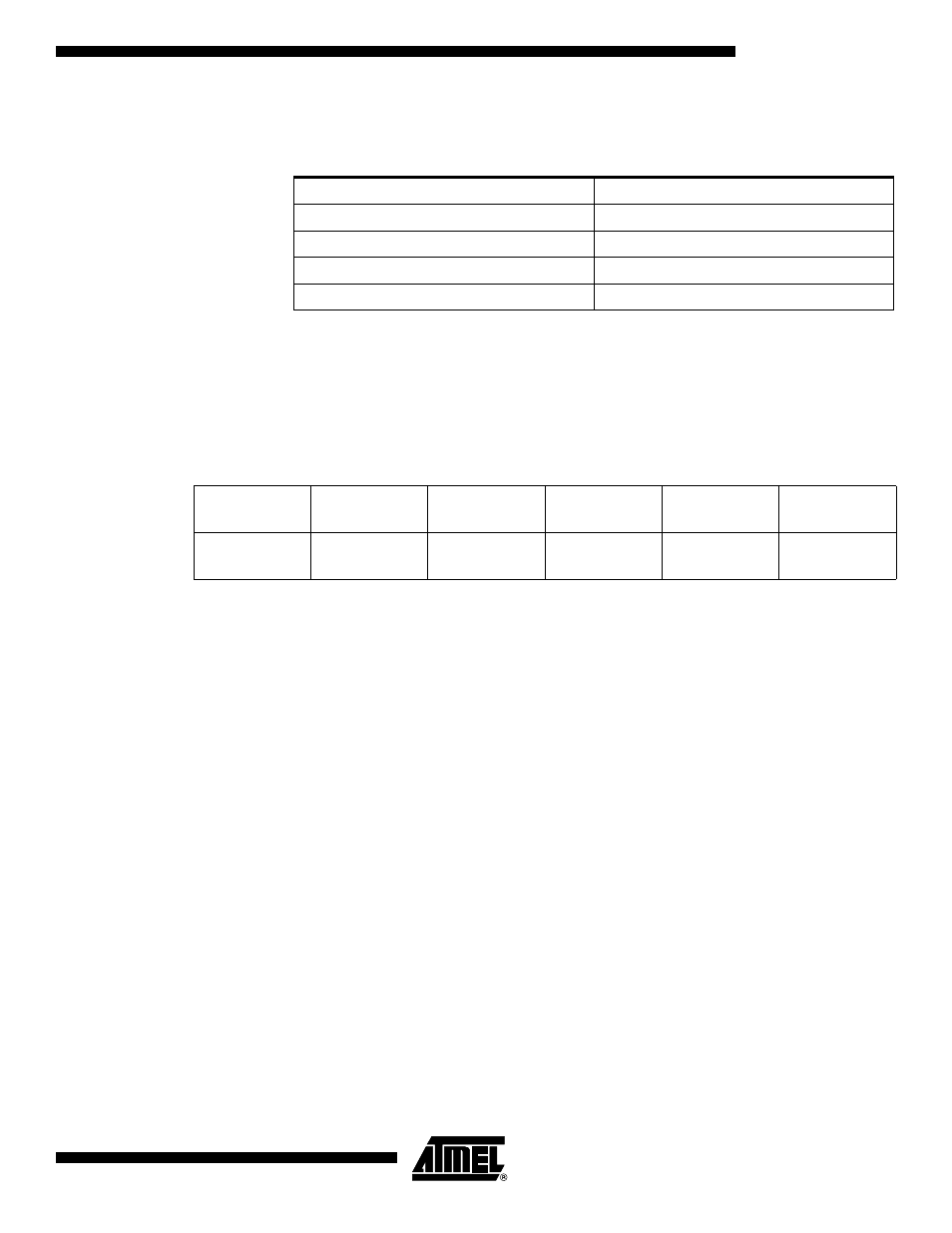
• Bits[6:5]: AVR System Clock Select
These bits select the divide value of the XTALB input that is used to produce the AVR
System Clock.
This clock select value may be programmed on the fly by either the AVR processor in
normal operation or by an I/O write SPI command during SPI mode. Note that during
SPI mode, the I/O and serial programming logic runs at XTALB/16 frequency.
• Bit[4]: Test Mode
When this bit is set to “1”, the part enters test mode. The I/O pins, if enabled, assume
the following functionality:
Notes:
1. IO_ENAB register is NOT used for SPI pins.
2. In SPI mode, the I/O registers may be directly accessed via the SPI interface. Txkey, lockdetect may be output using this
mode.
• Bit[3]: Battery Dead
Indicates battery is dead. Only readable by SPI interface.
• Bit[2]: Battery Low Indicator
This bit is identical to Bit[7] of Battery Low Configuration Register ($35). When Bit[6] of
Battery Low Configuration Register ($35) is set (Battery Low Valid), a set bit in this loca-
tion indicates that the battery voltage is lower than the voltage level that is determined
by Bits[5:0] of Battery Low Configuration Register ($35).
• Bit [1]: Sleep Bit
When set, this bit stops the crystal oscillator. This stops the AVR processor with the pro-
gram counter frozen at the current instruction. Sleep will also stop the Watchdog Timer.
The Watchdog Timer is only restarted if the part wakes up. If an I/O pin is configured as
a button, a button press will start the oscillator and check the battery level. If the battery
level is greater than the Battery Dead level, the AVR system clock is started and normal
program execution continues. If the battery level is below the Battery Dead level, the
crystal oscillator is turned off, putting the part back to sleep until a button is pressed
again (care should be taken not to put the part to sleep unless a button is configured and
enabled).
• Bit[0]: Button Boot Mode (BBM)
If the BBM bit is set and the part is brought out of sleep mode by a button input activa-
tion, the part will enter the button reset state. In this state, the part will reboot and begin
code execution at the reset location. This bit is reset at POR and when exiting the button
reset state. All other registers remain unchanged.
ACS[1:0]
AVR System Clock
11
XTALB/16
10
XTALB/32
01
XTALB/64
00
XTALB/128
I/O5
I/O4
I/O3
I/O2
I/O1
I/O0
Normal Mode
(RESETB = 1)
txkey
(Output)
lockdetect
(Output)
txenable
(Output)
RFU
RFU
RFU
SPI Mode
(RESETB = 0)
txkey
(Output)
lockdetect
(Output)
txenable
(Output)
SPI_CLK
SDO
SDI