3 short description of the interface rs 485, 3short description of the interface rs 485 – VEGA VEGACOM 557 Profibus DP User Manual
Page 81
VEGACOM 557 Profibus DP
81
Supplement C
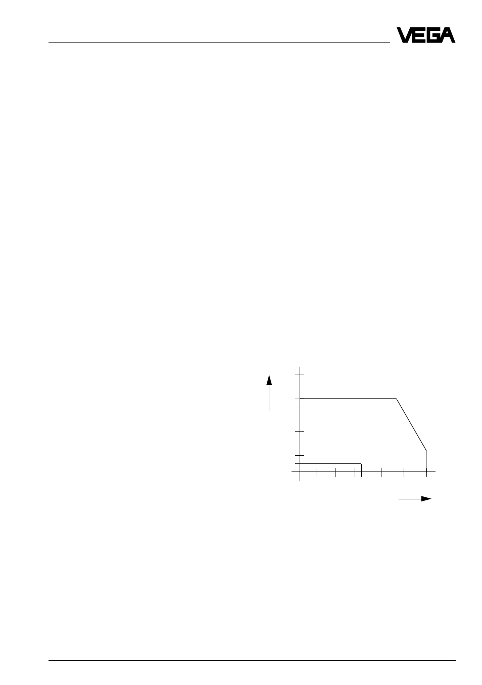
10 km
1,2 km
1 km
100 m
30 m
15 m
100
1 k
10 k 20 k
100 k
1 M
Bit/s 10 M
RS 422-A
RS 485
RS 232-C
Distance
Transmission rate
3
Short description of the interface
RS 485
The standard interface RS 485 used in
VEGACOM 557 Profibus DP transmits the
data serially and asynchronously in bit form.
Thereby the conditions "0" and "1" are trans-
mitted (without ground reference) by defined
voltage differences between two cables.
Usually, the dif ferential voltage of
-3...-6V corresponds to a logic "1". A logic
„0“ is shown by a differential voltage of
+3...+6V.
The advantage of this voltage difference
transmission is that possible common-mode
interferences cause a symmetrical shifting of
the voltage level and cannot distort the useful
signal.
Due to the higher interference resistance
compared to RS 232, distances up to 1200 m
and high data rates up to 12 Mbits can be
reached. The interference resistance is also
visible on the permissible voltage levels: at
an output level of the emitter under load of
±2 V, the r eceiver components r ecognise the
level of ±200 mV still as valid signal.
With higher transmission rates and/or larger
distances, a termination (adaptation of the
wave r esistance) is necessar y.
The bus system can include up to 32 partici-
pants, i.e. 1 Master and 31 Slaves. A protocol
ensures that at any time max. one participant
is active as emitter , whereas the others ar e
passively switched. An advantage is that one
cable pair, which can be used in alter nating
mode is sufficient for emission and receipt.
A galvanic separation of the emission/receipt
components is highly recommended, to stay
unaffected by potential shifts (which cannot
avoided with larger distances). A termination
is generally necessar y, independent of data
rate and distance.
Main characteristics of RS 485 interfaces are:
- long cable length
- high data rates
- basis for bus systems
Chart: Comparison of important interface
data
Interfaces
RS 232 C RS 422 A
RS 485
Transmission
asym.
symmetr. symmetr.
Number of drivers
1
1
32
Number of receivers
1
10
32
Transmission distance
15 m
1200 m
1200 m
max. transmission rate
20 Kbit/s
12 Mbit/s 12 Mbit/s
Emitter
Permissible driver
output voltage
±25 V
-0.25…6 V -7…12 V
Driver output signal
- without load
±15 V
±5 V
±5 V
- with load
±5 V
±2 V
±1.5 V
Receiver
Input voltage
±15 V
±7 V
-7…12 V
Sensitivity
±3 V
±200 mV ±200 mV
Diagram: Distance –– Transmission rate